Mesh optimization in Treble SDK
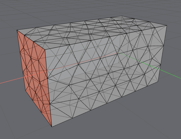
A tetrahedral mesh is a collection of connected non-uniform triangular pyramid elements, also known as tetrahedrons.
The Treble engine makes use of higher-order Discontinuous Galerkin (DG) method, for which the tetrahedral elements need to be resolved with more than 4 nodes. For the 4th order used in Treble there are 35 nodes per tetrahedron element, which are automatically created on and inside each element to allow for the higher order calculation.
The generation of a tetrahedral mesh is typically based on the highest selected frequency for dg, or the crossover frequency for the hybrid method. Simulations that are ga only do not need the calculation of this mesh. This tetrahedral mesh is characterized by a series of boundary surface meshes corresponding to the material assignment and a volumetric mesh in the remaining internal space.
The triangular boundary surfaces meshes share vertices with the tetrahedrons of the volumetric mesh. This page refers to both as mesh.
Mesh optimization
The volumetric meshing procedure used in the Treble engine is highly optimized for generating both accurate and optimized meshes for time domain calculations used in the Treble engine.
The Treble engine supports both interior holes in the mesh, corresponding to internal volumes, as well as interior surfaces in the mesh, corresponding to interior open surfaces. These will simply be resolved as interior boundary elements, where the boundary conditions assigned to the surface will be active on both sides of the boundary.
When modeling acoustics, the domain of interest is very often the interior of a space that is filled with a fluid, such as air. Therefore, the tetrahedral mesh quite often consists of a rather large interior volume, where tetrahedrons are mostly connected to other tetrahedrons. However, at the boundaries of the domain, there are "open" triangular surfaces, which represent the connection between the air and the surfaces of the space. These surfaces are the "boundary elements" of the volumetric mesh, on which material properties are applied.
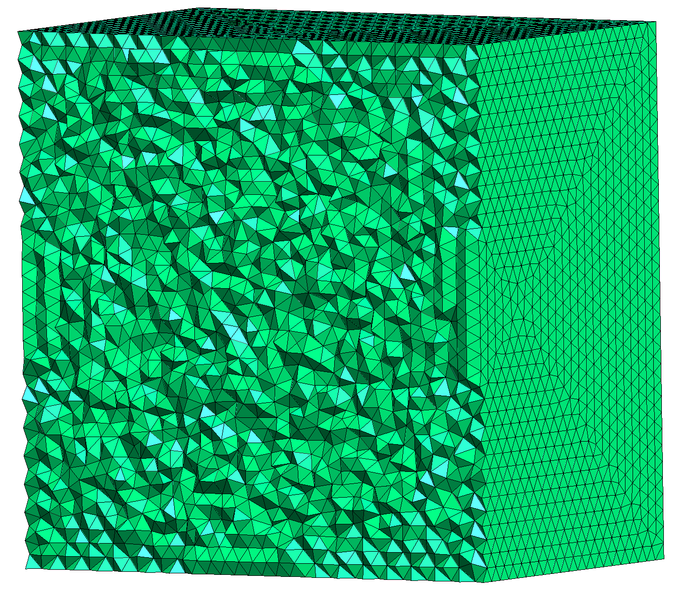
The size and the shape of the elements matter both for the computational accuracy and efficiency of the calculation. Since the Treble engine solves the wave equation in the time domain, there are generally 3 important metrics to have in mind when meshes are created:
- The average and maximum element edge length (from corner to corner).
- The total number of elements.
- The smallest height of an element (from base to tip).
Average edge length in tetrahedrons
The general sizing of the mesh is measured by the edge length of the elements in the mesh. The edge size of the tetrahedrons governs the acoustic response maximum frequency that can be computed from the mesh, following a linear correlation between the wavelength and the edge length. While the Treble engine takes care of choosing the right mesh sizing, it is still important to know for each doubling of frequency there will be an 8-fold increase in the number of tetrahedrons, since the edge length is halved in 3 dimensions.
Since it isn't possible to fill a domain with regular tetrahedrons (all edges with the same length), tetrahedrons generally have non-uniform edge sizes throughout the mesh.
The mesher used in the Treble engine is optimized to generate a tight distribution of edge lengths, as the longest edge length in the mesh governs the upper frequency limit.
Due to the non-uniform distribution of the mesh edge lengths, the cutoff between the valid and invalid frequency range and dispersion can accumulate at the frequencies where the mesh is not valid.
The Treble engine ensures that the mesh sizing and distribution always produces a valid response.
Number of elements
The total number of elements governs how much computation needs to be performed to compute one timestep in the simulation. As noted above, the number of elements scales quite dramatically with the frequency, but the number of elements will also scale linearly with the volume of the domain. The number of elements generally affects the computation time in a linear fashion: twice the number of elements requires twice as much computational effort.
Timestep and smallest tetrahedron height
The last, and probably most important, detail to consider is the relationship between time-step and computational stability. The stability of the computation is approximately derived from the sampling rate of the simulation and the smallest height of any tetrahedron in the mesh. The smallest height of a tetrahedron is measured from the base plane (side with the largest area) to the tip of the tetrahedron.
This means that the computational efficiency is very sensitive to small features and narrow gaps between objects in the mesh, in which almost flat tetrahedrons will appear. The Treble wave-solver compensates for small tetrahedrons to maintain stability constraints, so a small mesh element will not impact the accuracy of computation. However, in exchange, a single squashed tetrahedron in the mesh will significantly impact the computational efficiency.
Flat tetrahedrons
There are a few options available to control the mesh in the Treble SDK. In the case of a flat tetrahedron, often the best practice is to fix the input geometry. The flat tetrahedrons mostly occur where there are small distinct features in the mesh, such as a thin object (a kitchen countertop, a table) or a small gap between two objects. In these cases it is always recommended to go back to the input geometry, resolve these issues and reimport the geometry. See Geometry tips and tricks for more details on how to optimize input geometries (in SketchUp or any other modelling tools).
Mesh quality examples
The parameter defined in Treble as mesh quality, or more exactly mesh efficiency, is measured as a 2-digit percentage of how the minimum characteristic length differs from the optimal characteristic length for a given mesh size (controlled by the transition frequency).
Here the optimal mesh size depends on the crossover frequency and the optimal number of elements per wavelength.
The characteristic length is the tetrahedron volume divided by its maximum area.
The optimal characteristic length is the mesh size as above divided by 3.76, corresponding to the characteristic length for an equilateral tetrahedron with a side of mesh size.
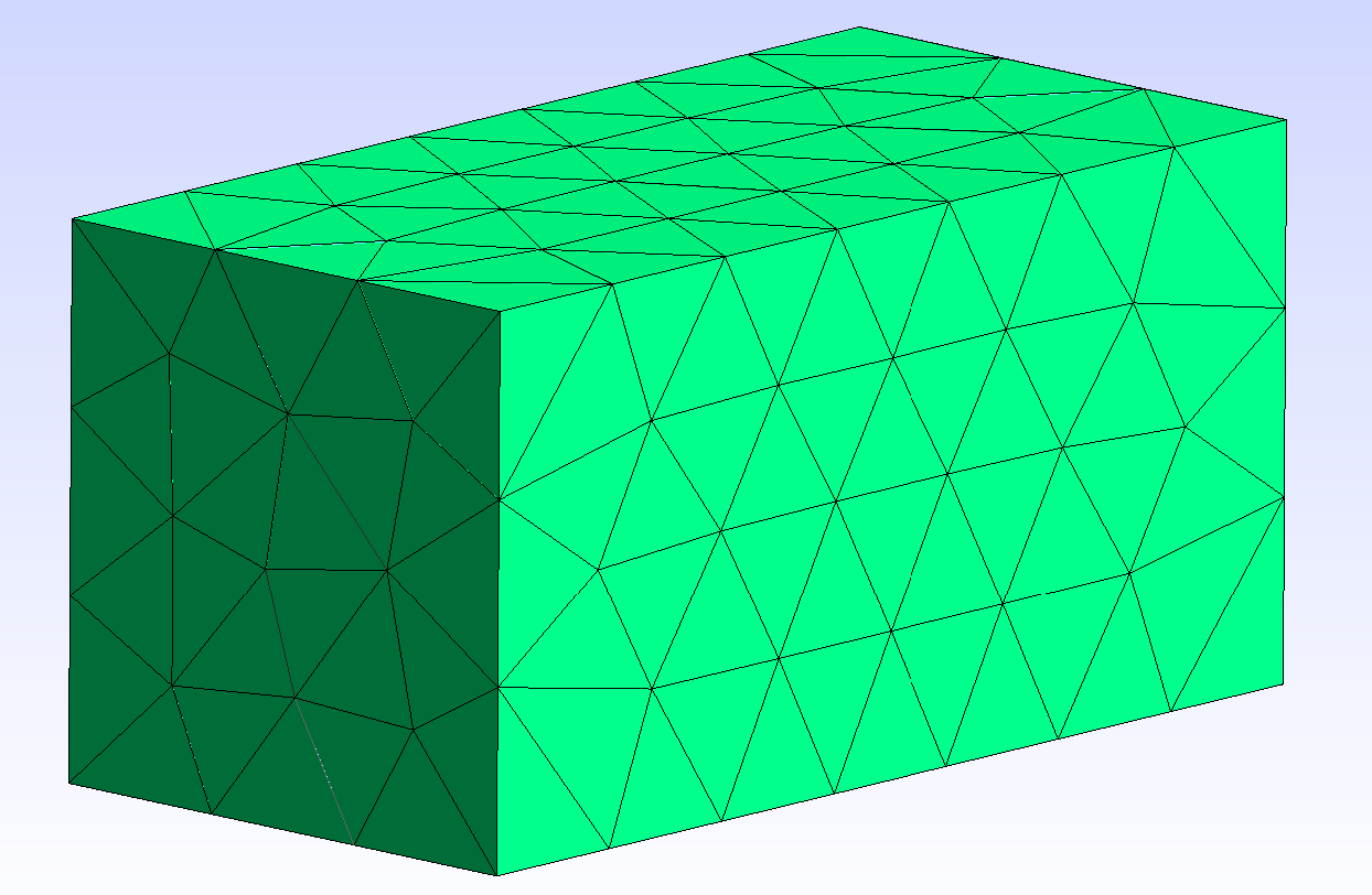
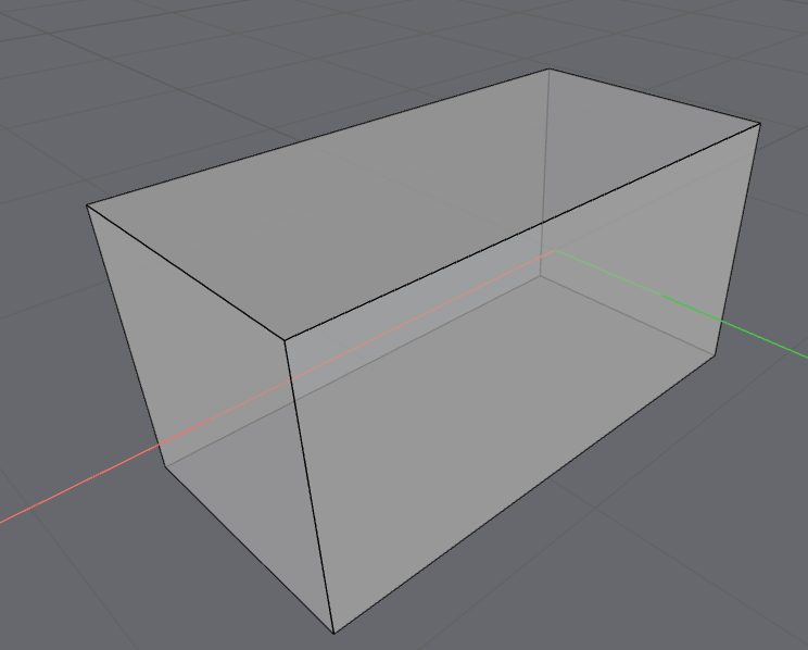
Think of creating an empty box of size 1 m × 1 m × 2 m. You then create a mesh with a 360 Hz crossover frequency.
The mesh efficiency or quality for the room as per above will be 100% at 360 Hz and the number of elements will be 86. If you increase the crossover frequency to 720 Hz, the mesh efficiency will still be 100%, but the number of elements will be much higher, growing with a factor of 8 ().
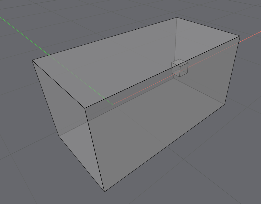
If you add a box of 25 cm inside your model and set a simulation with the same crossover frequency, the resulting mesh quality will still be 100, but the number of elements will be higher.
| n | 1 m × 1 m × 2 m | Box edge | Crossover frequency (Hz) | Element count | Element min height (m) | Mesh efficiency (%) |
|---|---|---|---|---|---|---|
| 1 | empty | / | 360 | 86 | 0.261983 | 100 |
| 1 | empty | / | 720 | 647 | 0.152038 | 100 |
| 2 | w/ box | 25 cm | 720 | 624 | 0.145386 | 100 |
| 3 | w/ box | 13 cm | 720 | 796 | 0.087693 | 73.14 |
| 4 | w/ box | 15 cm | 720 | 765 | 0.104711 | 87.33 |
| 5 | w/ box | 15 cm | 891 | 1182 | 0.094743 | 97.79 |
| 6 | w/ box | 15 cm | 892 | 1143 | 0.098464 | 100 |
The parameter element min height represents the minimum tetrahedron height that the mesh should have for a given crossover frequency. In example 4, the internal box has a side edge of . For a crossover frequency of 720 Hz, the element min height will be . You can reconstruct the min tetrahedron side length with the following formula.
The result will be .
You can then find the maximum wavelength that you can simulate for tetrahedra of this size by multiplying a factor of 3.
To find the maximum crossover frequency you divide the speed of sound by the wavelength.
In example 5 you use as a crossover frequency for the element min height previously calculated. You obtain a mesh quality of 97.79%.
In example 6 you use , and the mesh quality becomes 100 %.
This example demonstrates that to improve the mesh quality / efficiency percentage, you should try to create geometries with fewer details.
Do not increase the transition frequency unless needed for valid sampling reasons, since it will automatically cause the creation of a larger number of smaller elements, therefore increasing the computing time.
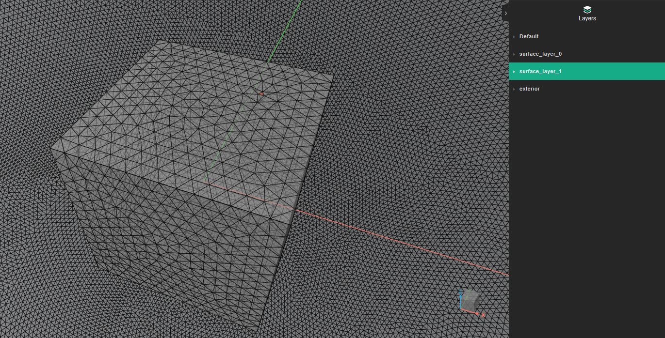
The example below shows the surface meshing for a device with a 1 m box size. The loss of mesh efficiency highlighted in the table above is due to the small elements that host the microphone placements.