Setting up a Device Simulation
When setting up a simulation to create a device within Treble, we offer two different interfaces. A simplistic, easy to use, interface and a more elaborate and customizable one. The simplistic interface is the recommended one for most cases, but we can, however, not guarantee that it will work correctly for elaborate geometries that cause resonances and need long impulse responses to be fully captured. For such devices, we recommend using the elaborate interface.
A device simulation is a free-field simulation where one or more microphones are placed on the device which is put into the center of the free-field simulation. A single simulation is run for each of the microphones where the source is placed at each microphone location, respectively.
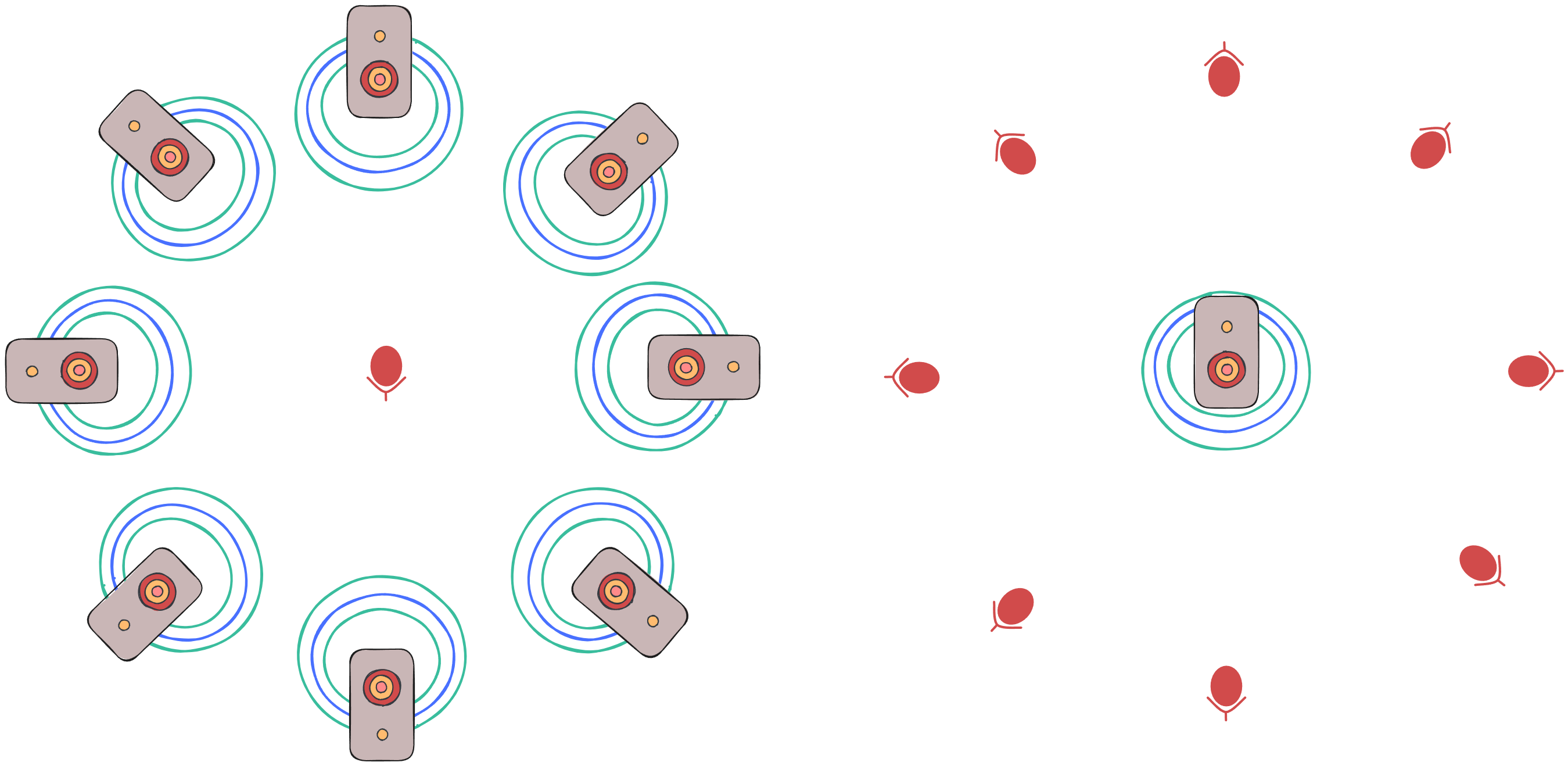
The data we need is what is illustrated on the left side of the figure above, where each source is fired individually and recorded in the middle. We can, however, utilize the reciprocal nature of wave propagation to create the same data by using the scenario illustrated on the right side. By doing that we limit the number of simulation to the number of microphones on the device in question rather than the hundreds of sources required for the scenario on the left. In an ideal scenario (on the left side) the sources are far away and resemble plane waves upon arrival at device location. To replicate such an ideal scenario in the simulated reciprocal case (on the right side), we offer (and recommend) the option to do a far-field expansion on the simulation results when creating the DRTF.
When setting up such a simulation, there are a few tunable parameters.
- Radius of the spherical geometry
- Here the goal is to set the sphere geometry in such a way that all the energy coming from the source reaches all receivers but does not reflect of the edge and come back to the receivers.
- The larger the sphere, the more expensive the simulation gets, so it's in your interest to make it as small as possible.
- The needed size of sphere is frequency dependent as the source width and delay are frequency dependent.
- Radius of receiver sphere
- In a sense, the larger, the better. However, with computational interest in mind, we find that a radius of 1 m is generally sufficient.
- IR length
- Temporal length of the impulse response to be computed.
- This ties to the size of domain, receiver sphere and device geometry.
- A balance between getting all energy to receivers and not getting a reflection back from the exterior surface.
- Upper frequency of simulation
- The device will, at maximum, be valid up to this frequency
- The simulation cost increases rapidly with frequency, so in general it's good to test things at lower frequencies first.
- Ambisonics order
- In the simulation, this controls the number of receivers which are distributed around the device
- From the simulation results you will be able to create devices at an equal or lower order than the simulation accounted for.
- We have a guide for choosing an appropriate ambisonics order
- Number of receivers
- The number of receivers can be tuned, otherwise they follow the ambisonics order.
- Mesh parameters
- Meshing parameters, which will not be detailed here, can be tuned for improving the representation of the device geometry in the simulation
These parameters are non-trivial to tune, but the good news is that you do not have to worry about most of them. In the simple interface, these parameters, except for the ambisonics order and upper frequency are tuned for you.
Simple Interface
Using the simple interface, you can set up and run a device creating simulation in just a handful of lines of code. You need to provide the device geometry, or a path to a file containing the geometry, and you need to define where on the device the microphones should be located.
device_geometry = "some_device_file.3dm"

microphone_placements = [treble.Point3d(0.1, 0.0, 0.0), treble.Point3d(-0.1, 0.0, 0.0)]

simulation_definition = project.setup_drtf_simulation(
    simulation_name="some_device_creation",
    device_geometry=device_geometry,
    freefield_model_name="ff_model_for_some_device",
    device_microphone_placements=microphone_placements,
    frequency=6000,
    ambisonics_order=16
)
This tunes all the previously mentioned parameters automatically in a way that it works in a somewhat optimal way for most cases. However, as mentioned previously, it's not guaranteed that it works for devices which cause resonances and late arrivals of energy. From this simulation definition, it can be plotted for closer inspection, added to the project and finally, started.
simulation_definition.plot()
simulation = project.add_simulation(simulation_definition)
simulation.start()
The simulated device can then be used to create a DRTF, to be used for device rendering.
Customizable Interface
When using the customizable interface, a great care has to be taken to tune the input parameters that were mentioned above correctly.
The first step is to create the free-field model.
When doing that, you have the option to tune the sphere_geometry_radius, injected_triangle_edge_length, and receiver_sphere_radius_in_m.
These do all have default settings, and sphere_geometry_radius gets tuned dynamically if frequency and device_microphone_placements are passed to the model creation.
# Optional
ff_settings = treble.free_field.FreeFieldModelSettings(frequency=2000, receiver_sphere_radius_in_m=1)

mics = treble.free_field.DeviceMicrophonePlacements(
    list_of_points = [treble.Point3d(0.1, 0, 0), treble.Point3d(-0.1, 0, 0)],
    injected_triangle_edge_length = 8e-3 # Optional
)

ff_m = treble.free_field.add_free_field_model(
    project=project,
    name="ff_model",
    geometry="path_to_device_geometry",
    device_microphone_placements=mics,
    freefield_model_additional_settings=ff_settings
)
At this point, you have a model which can be plotted and analyzed as per usual with other models in the Treble SDK.
Now it's time to create a FreeFieldSimulationDefinition using the already generated model.
For that step, you need to tune the number_of_receivers, max_ambisonics_order and some mesher parameters.
These all have default value, but as this is presenting the customizable interface, we'll customize them.
# Optional
ff_sim_settings = treble.free_field.FreeFieldSimulationSettings(
    number_of_receivers=1200,
    max_ambisonics_order=16
)

mesher_settings = treble.MesherSettings(simplify_mesh=False)
When looking at / plotting the ff_m model, you can see the layers which microphones have been placed on, and you can tune specific mesher settings for those layers if you belive that to be of interest for you.
Normally, it's fine to leave this to the default values though.
# Name of source (microphone) layers
source_layers = ["surface_layer_0", "surface_layer_1"]

local_sizing = [
    treble.LocalMeshSizing(
        layer_name=surface_layers[i], mesh_sizing_m=8e-3, keep_exterior_edges=False
    ) for i in range(len(surface_layers))
]
We now have all the information we need to create the FreeFieldSimulationDefinition
sim_def = treble.free_field.FreeFieldSimulationDefinition(
    name="free_field_simulation",
    free_field_mode=ff_m,
    frequency=6000, # If passed before, has to be the same
    receiver_sphere_radius=1, # If passed before, has to be the same
    simulation_purpose=treble.free_field.FreeFieldSimulationPurpose.device,
    free_field_simulation_settings=ff_sim_settings,
    mesher_settings=mesher_settings,
    local_mesh_sizing=local_sizing
)
Now similarly as in the simple interface, the simulation definition can be plotted, added to the project and run.
sim_def.plot()
simulation = project.add_simulation(sim_def)
simulation.start()
The simulated device can then be used to create a DRTF, to be used for device rendering.