Importing Device Geometry
This guide aims to make it clear what the supported file formats of the Treble SDK are and how to export file formats from native CAD applications so that they can be used to generate Device Related Transfer Functions (DRTF) specific to the geometry imported.
General recommendations
File formats accepted
Treble SDK currently allows to import NURBS from Rhinoceros, as well as already meshed objects.
The geometry to be imported should be drawn in meters in one of these file formats:
- .3dm (NURBS or 3D mesh)
- .obj (3D mesh)
- .dxf (3D mesh aka 3DFACE)
Single layer
The material will be automatically assigned to the entire device. If the geometry is organized within different layers, we recommend making a copy of the file for export, select all the objects and move them to one layer only.
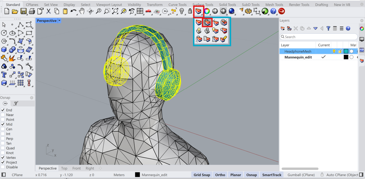
In the example below, we see the HeadphoneMesh selected. By clicking the layered cake slice icon, we can acess the change layer command. We click the button with the arrow and then we select the layer of the Mannequin.
Joined geometry
The process of creating the DRTF for the device needs a geometry that should appear as a boolean union of the different parts. Separate volumes should be avoided as the meshing algorithm might automatically discard volumes external to the main one if they are not intersecting with each other.
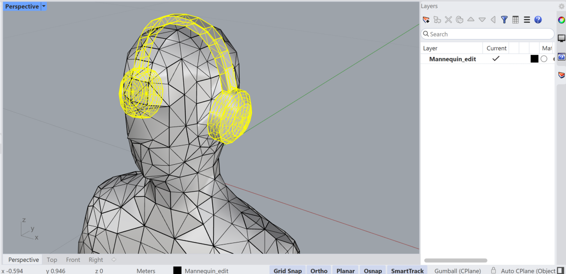
In the image below we see how the headphones are still disjointed from the rest of the mannequin.
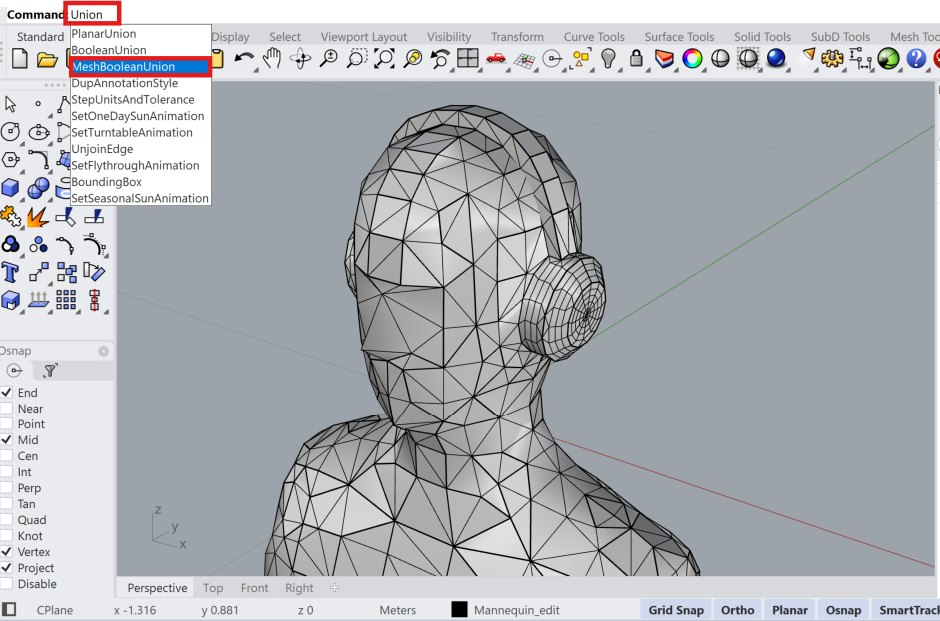
We type Union in the command line and select Mesh Boolean Union. We then select the headphones and the mannequin and confirm. The resulting geometry is now a single object.
When the geometry is exported as .STL (and later converted to .OBJ or .DXF) all the parts will be automatically placed on one single layer and the creation of a single watertight volume will be attempted. The two steps above should therefore not be needed.
Thick geometry
When importing the geometry, it is possible to add a simplificationThreshold in the settings with the geometry_checker_settings argument. We recommend to avoid importing geometries whose thickness is inferior to this threshold. This might cause excessive simplification or the removal of some parts. When omitted, the default simplificationThreshold is set as 5 mm, as shown in the example below.
ff_m = treble.add_free_field_model(  # Creates the freefield model
    project=project,
    name=freefield_model_name,
    geometry=device_model_path,
    sphere_geometry_radius=sphere_geometry_radius,
    device_microphone_placements=mics,
    freefield_model_additional_settings=ff_settings,
    geometry_checker_settings=GeometryCheckerSettingsDto(
        simplificationThreshold=0.005
    ),
)
Tutorials
We prepared the following tutorials to aid the process of exporting a geometry from a CAD software suitable for use with the DRTF simulation feature.
Exporting a geometry from Solidworks
Exporting a geometry from AutoCAD
Exporting a geometry from Rhino
When importing NURBS from Rhinoceros, the level of detail of the mesh to be simulated is decided according to optimal visualization settings. We recommend in this case to make a copy of the file and join the surfaces all toghether prior to saving the file to import as device. This will ensure that the corresponding mesh will take into account intersections between parts.
If you want to decide the tessellation options yourself, you can use Rhino´s tools (Mesh, ReduceMesh, QuadRemesh) or your favourite plugins (Grasshopper, Weaverbird, etc.). We recommend to take into consideration the maximum frequency that is of interest for the simulation and consider simplifying elements smaller than a quarter of the corresponding wavelength (as a rule of thumb).
It should also be noted that the microphone placement works at best when it is away from the edges and positioned on a flat surface, so that there are no issues related to possible remeshing of the device surface.