Meshes in Treble SDK
When a dg or hybrid simulation is added to a project, a tetrahedral mesh is automatically calculated.
A tetrahedral mesh is a collection of connected non-uniform triangular pyramid elements, also known as tetrahedrons. The Treble engine makes use of higher-order Discontinuous Galerkin (DG) method, for which the tetrahedral elements need to be resolved with more than 4 nodes. For the 4th order used in Treble there are 35 nodes per tetrahedron element, which are automatically created on and inside each element to allow for the higher order calculation.
The automatic generation of a tetrahedral mesh is based on the highest selected frequency for dg, or the crossover frequency for the hybrid method. Simulations that are ga only do not need the calculation of this mesh. This tetrahedral mesh is characterised by a series of boundary surface meshes corresponding to the material assignment and a volumetric mesh in the remaining internal space.
The triangular boundary surfaces meshes share vertices with the tetrahedrons of the volumetric mesh. For simplicity, we will call here "mesh" both the volumetric mesh and the boundary surface meshes.
The mesh used in Treble for finite elements calculation (DG) adopts a definition of quality based on the following conditions:
- elements are as close as possible to regular tetrahedrons;
- elements are as homogeneous as possible in size and volume;
- elements do not have edges smaller than a certain length.
Creating a mesh
The creation of a mesh for user defined geometry is typically triggered by the command project.add_simulation(simulation_definition). Likewise this will happen when adding a simulation definition in the device import simulation workflow.
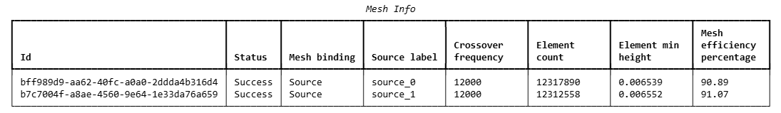
Plotting mesh info
After the DG mesh has been created, it is possible to plot a summary of its quality, based on the criteria previously addressed. Use the following command to plot in a table the general information about the mesh.
from treble_tsdk import display_data as dd

dd.display(simulation.get_mesh_info())
or
simulation.get_mesh_info().as_table()
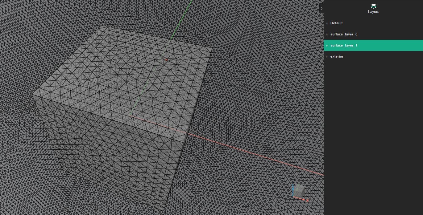
The following command will plot the boundary surfaces of the volumetric mesh, to help inspecting potential problems.
simulation.get_mesh_info().plot()
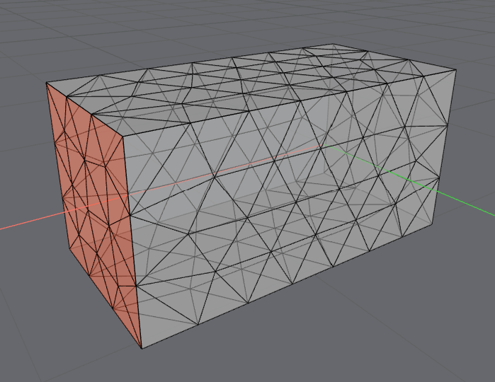
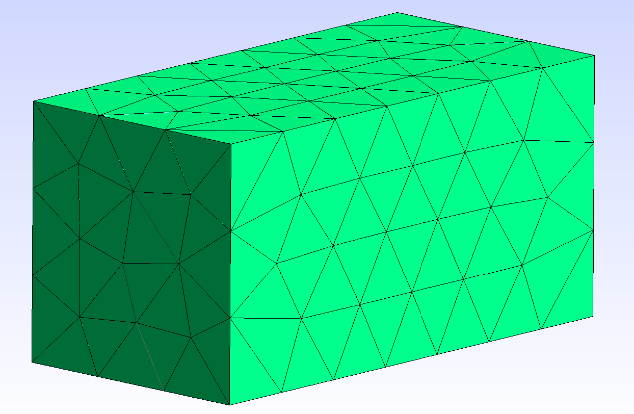
The example below shows the surface meshing for a device with a 1m box size. The loss of mesh efficiency highlighted in the table above is due to the small elements that host the microphone placements.
The plotting function can be used to evaluate how the input geometry is resolved in a boundary surface mesh. This is especially important when working with curved surfaces that are of high importance to the analysis, where it can happen that the meshing algorithm applies too broad a simplification to the curved geometry (especially when a low transition frequency has been chosen).
Mesh quality examples
The parameter defined in Treble as mesh quality, or more exactly mesh efficiency, is measured as a 2-digit percentage of how the minimum characteristic length differs from the optimal characteristic length for a given mesh size (controlled by the transition frequency).
Here the optimal mesh size depends on the crossover frequency and the optimal number of elements per wavelenght.
The characteristic length is the tetrahedron volume divided by its maximum area.
The optimal characteristic length is the mesh size as above divided by 3.76, corresponding to the characteristic length for an equilateral tetra with a side of mesh size.
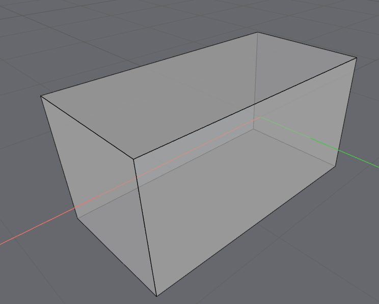
Let us consider the following examples. We have an empty box of size 1 x 1 x 2 m. We create a mesh with a 360 Hz crossover frequency.
The mesh efficiency or quality for the room as per above will be 100% at 360 Hz and the number of elements will be 86. If we now increase the crossover frequency to 720 Hz, the mesh efficiency will still be 100%, but the number of elements will be much higher, growing with a factor of 8 ().
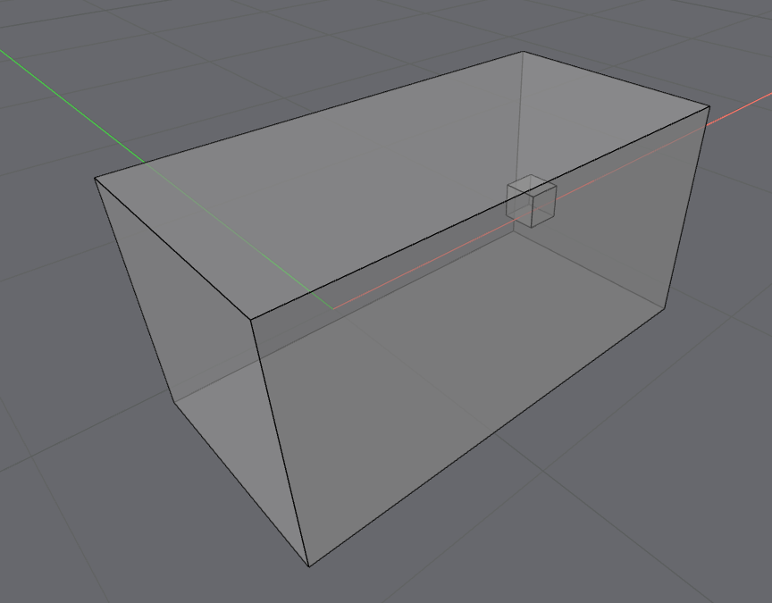
If we add a box of 25 cm inside our model and set a simulation with the same crossover frequency, the resulting mesh quality will still be 100, but the number of elements will be higher.
| n | 1x1x2m | Box edge | Crossover Frequency | Element Count | Element min height | Mesh efficiency percentage |
|---|---|---|---|---|---|---|
| 1 | empty | / | 360 | 86 | 0.261983 | 100 |
| 1 | empty | / | 720 | 647 | 0.152038 | 100 |
| 2 | w/ box | 25 cm | 720 | 624 | 0.145386 | 100 |
| 3 | w/ box | 13 cm | 720 | 796 | 0.087693 | 73.14 |
| 4 | w/ box | 15 cm | 720 | 765 | 0.104711 | 87.33 |
| 5 | w/ box | 15 cm | 891 | 1182 | 0.094743 | 97.79 |
| 6 | w/ box | 15 cm | 892 | 1143 | 0.098464 | 100 |
The parameter element min height represents the minimum tetrahedron height that the mesh should have for a given crossover frequency. In example 4, the internal box has a side edge of . For a crossover frequency of 720 Hz, the element min height will be . We can reconstruct the min tetrahedron side length with the following formula.
The result will be .
We can then find the maximum wavelength that we can simulate for tetrehedra of this size by multiplying a factor of 3.
In order to find the maximum crossover frequency we divide the speed of sound by the wavelength.
In example 5 we use as a crossover frequency for the element min height previously calculated. We obtain a mesh quality of 97.79%.
In Example 6 we use , and the mesh quality becomes 100 %.
This example demonstrates that in order to improve the mesh quality / efficiency percentage, we should try to create geometries with less details.
Increasing the transition frequency as a solution should not be done unless needed for valid sampling reasons, since it will automatically cause the creation of a larger number of smaller elements, therefore increasing the computing time.