Adding and editing receivers
A receiver represents the point in space where the impulse response will be simulated and analyzed. It acts as a "virtual microphone" that you place inside the space at the location where you want to measure or listen to the result.
There are two types of receivers available: Point receivers and Surface receivers. To add a new receiver, select the type you want (point or surface) and click the Add icon. The first receiver will appear in the center of the model, and each new point receiver appears 0.5m next to the last point receiver added, along the x-axis. The coordinates can then be edited in the sidepanel. You can create up to 100 point receivers and have up to 1199 grid points in total for surface receivers.
Point receivers
The point receivers are represented by blue dots in the 3D view. To find a specific point receiver, click the receiver row in the sidepanel and it will be selected in the 3D view.
Batch input and offset
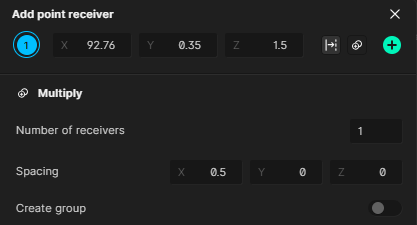
Multiple receivers can be created in a single operation using the batch creation feature. This is useful when you need to place a number of receivers with a regular pattern or spacing. To open it, select the downward-pointing arrow next to the Add split-button. This will open a new pop-up, in which you can both offset a receiver from a surface and input multiple receivers and space them out.
To offset a receiver from a surface select the offset icon. You can then select a surface to offset from using the dropdown or by clicking on a surface in the viewport. Note that you can offset a single receiver from multiple surfaces.

To generate multiple receivers select the multiply icon. You can then select how many receivers you want to input and space them out along the axis of the coordinate system. Additionally, you can add them all to a single group.
Receivers should be placed inside the model, at least 0.1 meters away from any surface and 0.5 meters away from any source. A receiver will turn red in the 3D view if it has an invalid position.
For each individual point receiver, spatial (second order ambisonics) impulse responses will be automatically created, which is what is used in the spatial audio processing in the auralizer. Both the mono and spatial IRs can be downloaded for each source-receiver combination.
Loading point receivers from file
It is also possible to read multiple receiver coordinates from a text file by pressing the three dots and selecting Load from file. Each line in the file should have three values for the X, Y and Z coordinates respectively.
The coordinates should be separated by a comma, for example:
2,2,3
2.5,2.5,3
3,2.5,2.5
Working with point receivers in a simulation
After creation, point receivers can be grouped, multi-selected, multiplied, moved and offset in the same way as sources as documented here
Surface receivers
The surface receiver function creates a cartesian grid across the surface, where a point receiver is placed at the center of each square. For each square, all acoustic parameters are calculated. Surface receivers are identified with the grey diamond icon in the viewport and sidebar.
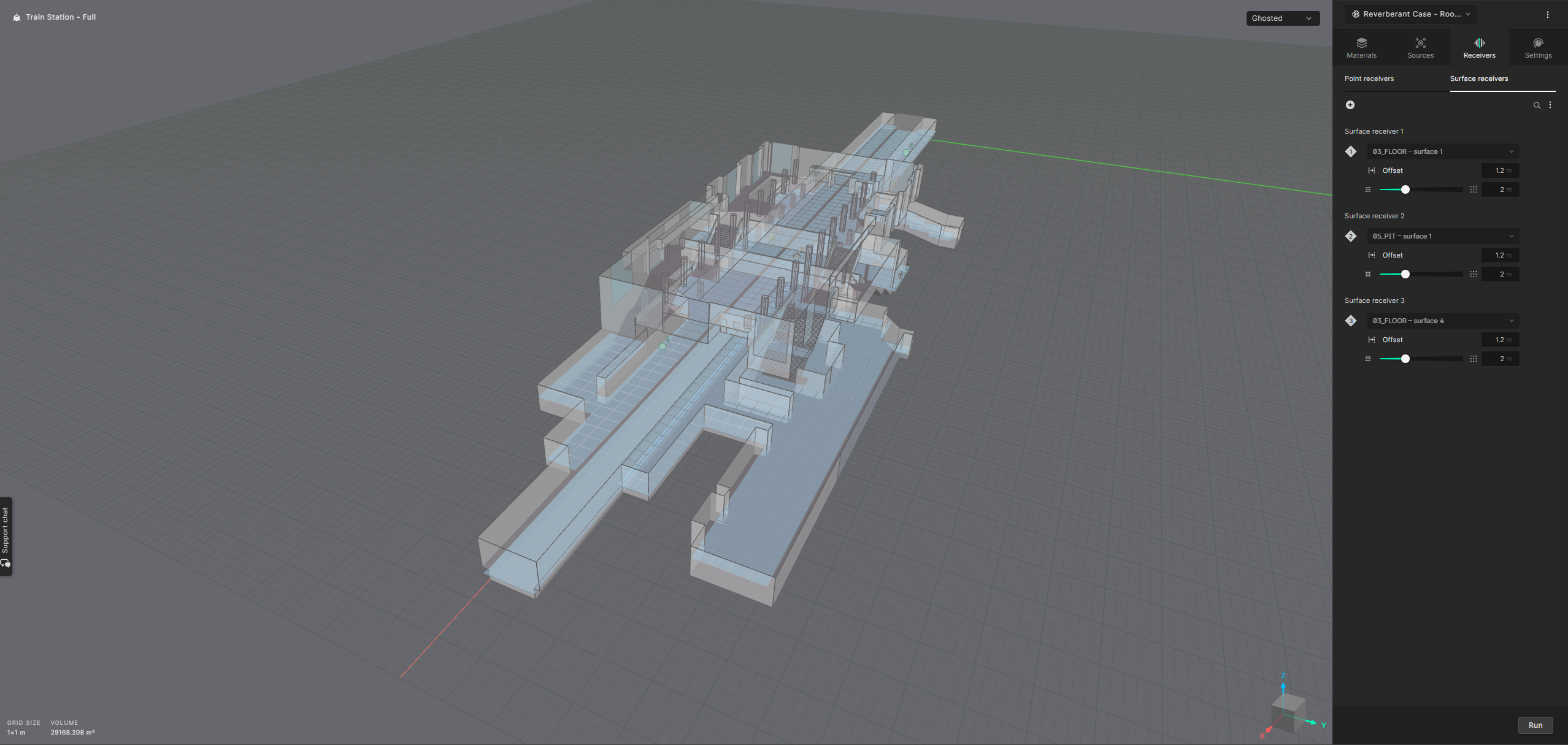
Surface receivers can be created in two ways, by offsetting from a layer (surface) or by creating a custom rectangular grid.
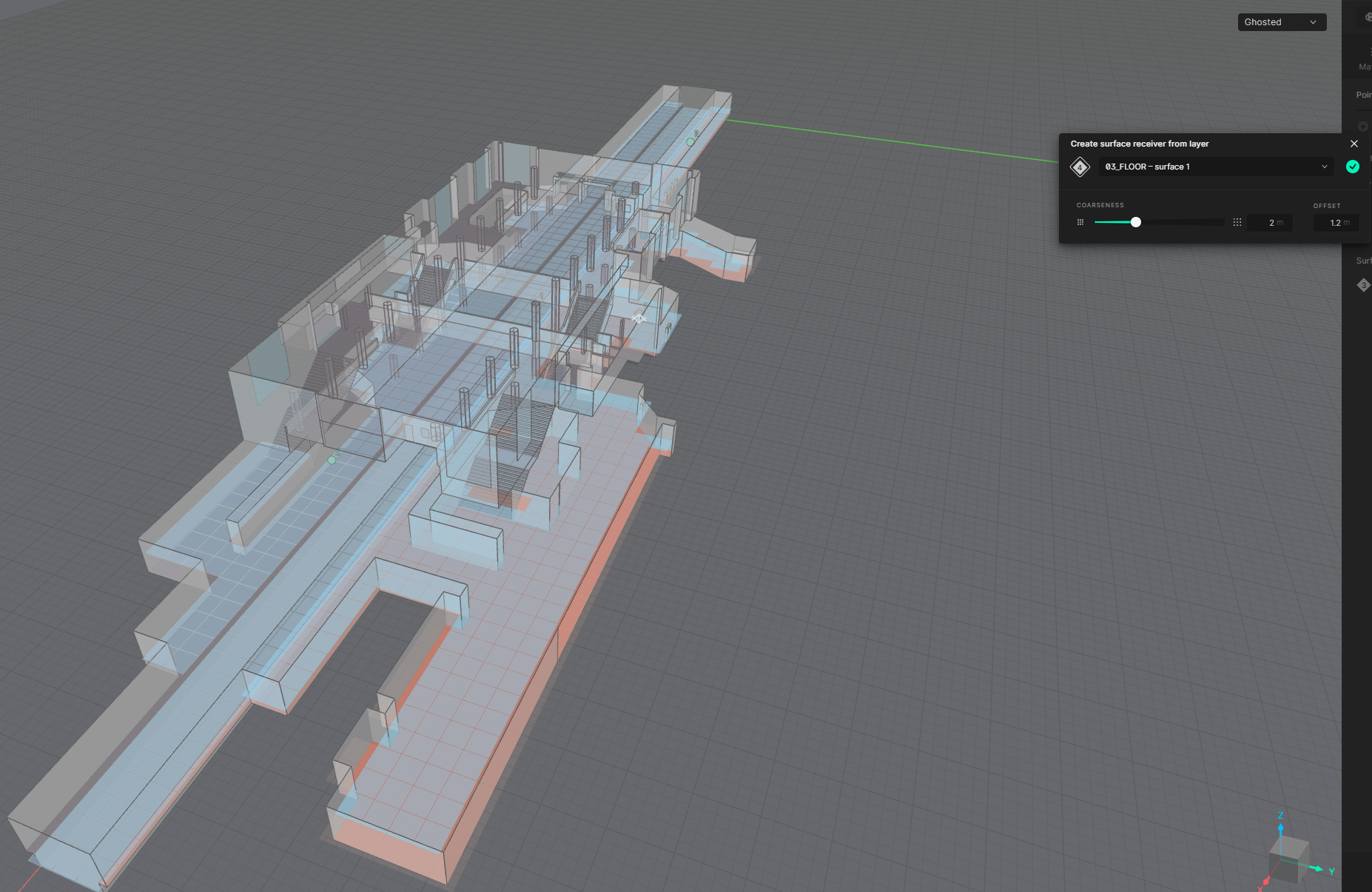
Create from layer

This option will create a surface receiver that mirrors the selected layer (surface) in the viewport.
You can then select a surface to offset from using the dropdown or by clicking on a surface in the viewport. It is then possible to set the offset distance along the direction of the surface normal of the layer.
The coarseness setting defines the distance (in meters) between the center points in the surface receiver grid. Coarseness can be set in incremental steps of 0.1 meters.
Create custom grid

For each surface receiver, define the X,Y,Z coordinates of its center point and its rotation along any of the three axes. The length and width options determine its overall size.
If a part of the surface is placed outside of the model, the invalid points of the surface will simply be disabled.
The final input is coarseness. This defines the distance (in meters) between the center points in the surface receiver grid. Coarseness can be set in incremental steps of 0.1 meters.
It is possible to hide the surface receiver in the viewport by selecting the "eye" icon on the right side of the input parameters. To delete a surface receiver, select the "trash can" icon to the right.
Working with surface receivers in a simulation
After creation, surface receivers can be multi-selected, multiplied, moved and rotated and offset using the floating toolbar at the bottom of the viewport.