Exporting a geometry suitable for DRTF generation from AutoCAD
AutoCAD is one of many CAD modelling tools that are used in the industry to generate geometry assemblies made of different parts. Other tools include Rhinoceros, Parasolid, Solidworks, Autodesk Fusion, CATIA, and many more. This guide demonstrates how to use AutoCAD to export a CAD file into a DXF file that can be imported as a device geometry in the SDK.
Although you can create a Mesh primitive with the shape of a cylinder, this guide shows how to mesh a 3DSOLID created from a curve and an extrusion.
Key steps:
- Create a simple shape in AutoCAD
- Convert the solid to surfaces
- Convert the surfaces to mesh
- Save the geometry as DXF
Create a simple shape like a cylinder in AutoCAD
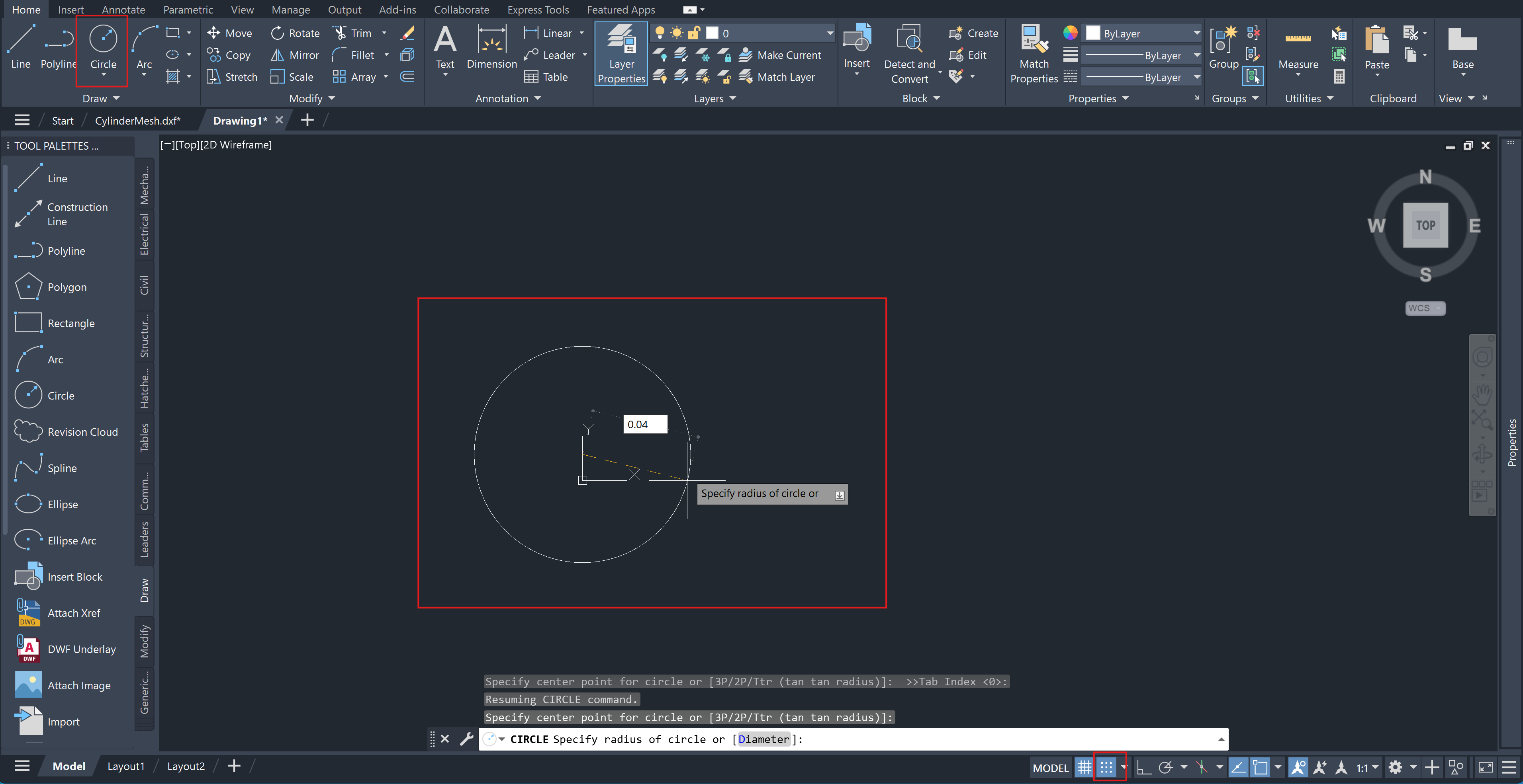
From the Home tab on the top left, select Circle.
Pick or type the origin point 0,0,0.
Set a radius by typing it or picking a point, for example 0.04. The unit is meters.
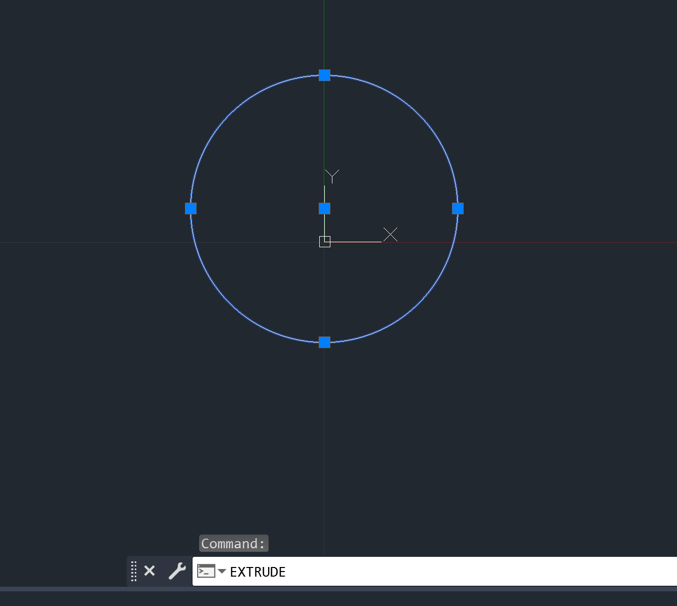
Next, select the Circle and type the command EXTRUDE.
Specify the height along the z direction, for example 8 cm as 0.08 meters.
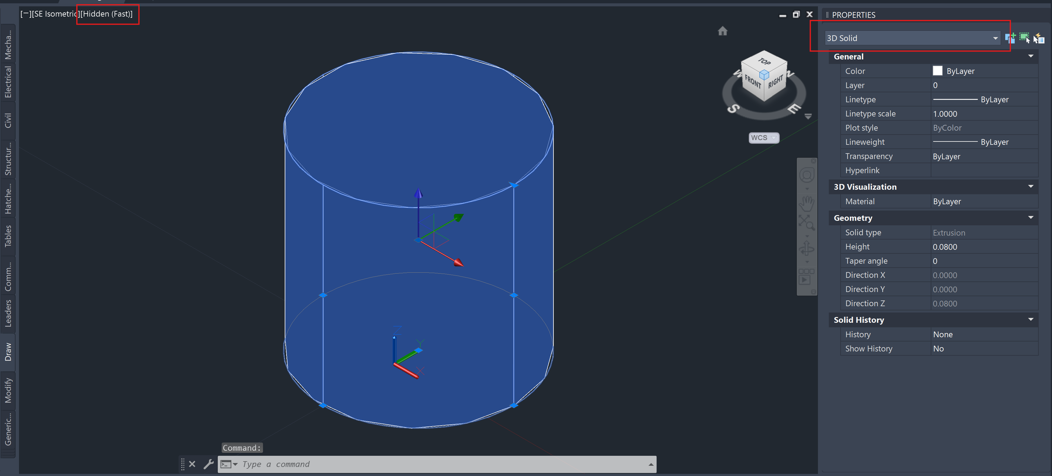
Changing the view angle using the navigator and switching the visibility to Hidden reveals the cylinder as a 3D Solid, with a series of handles that allow its modification. The geometry is listed as 3D Solid in the property inspector on the right.
Convert the solid to surfaces
Convert the solid to surfaces using the command CONVTOSURFACE.
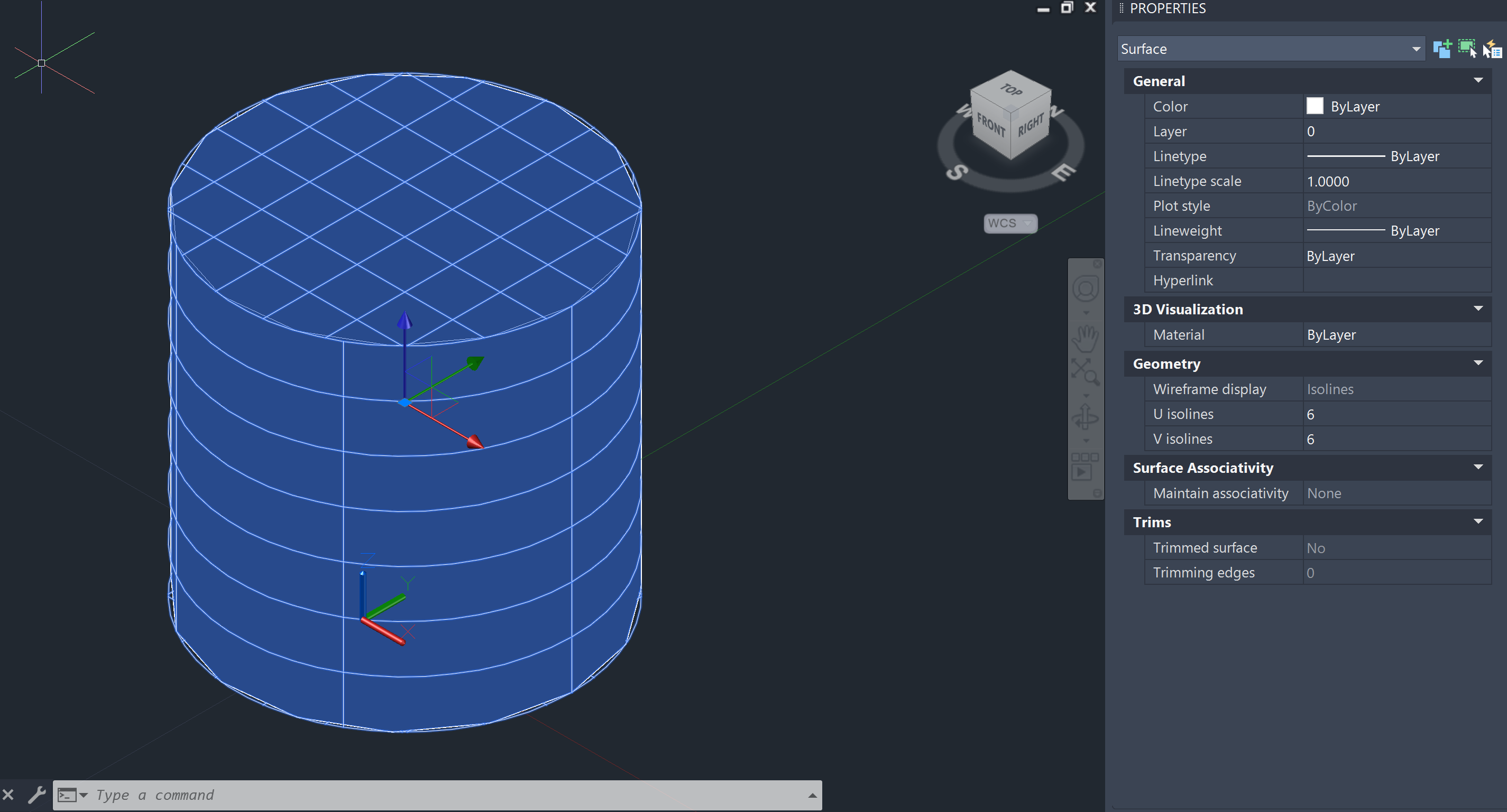
Convert the surfaces to mesh
Use MESHOPTIONS to transform the surface into a mesh.
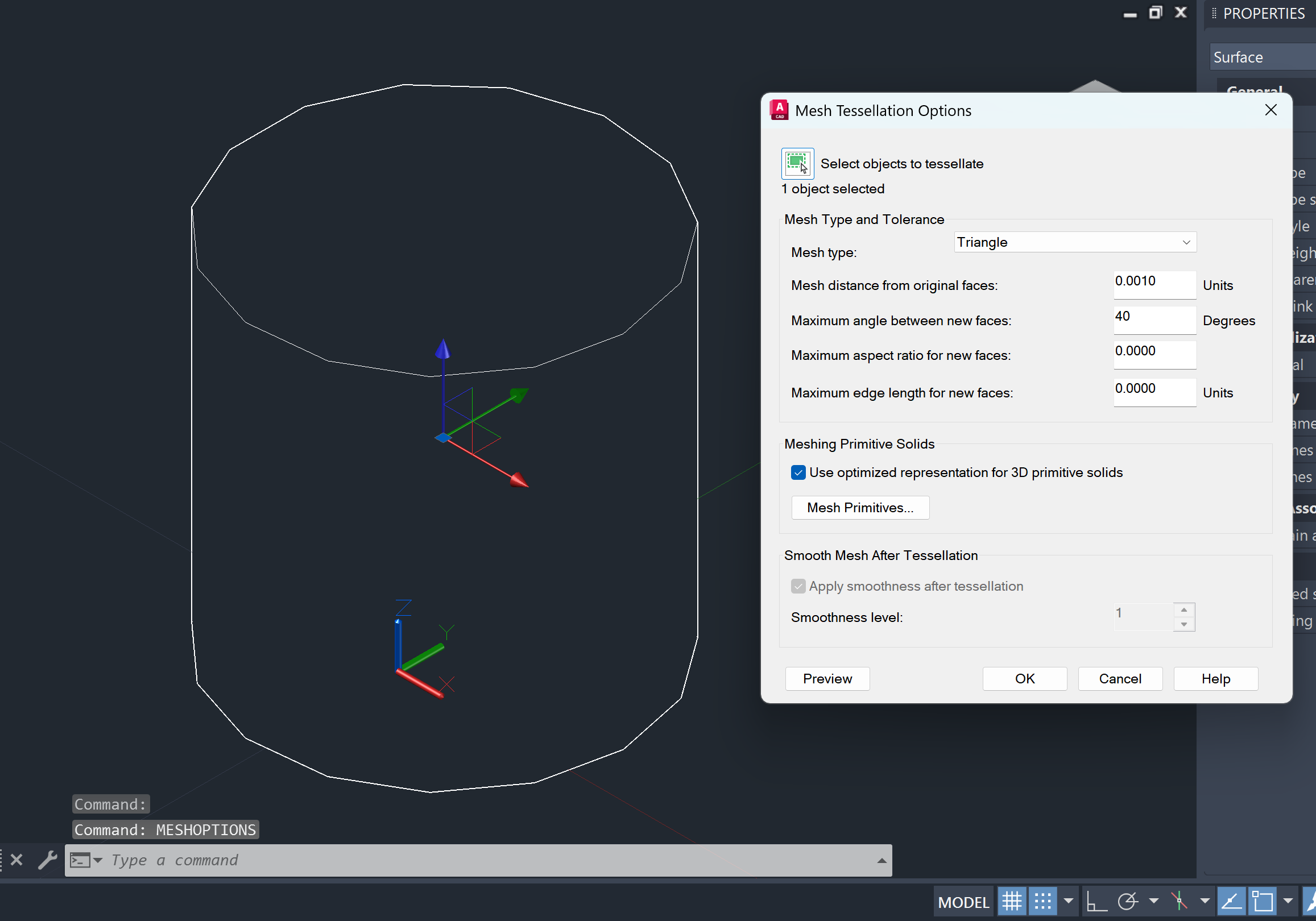
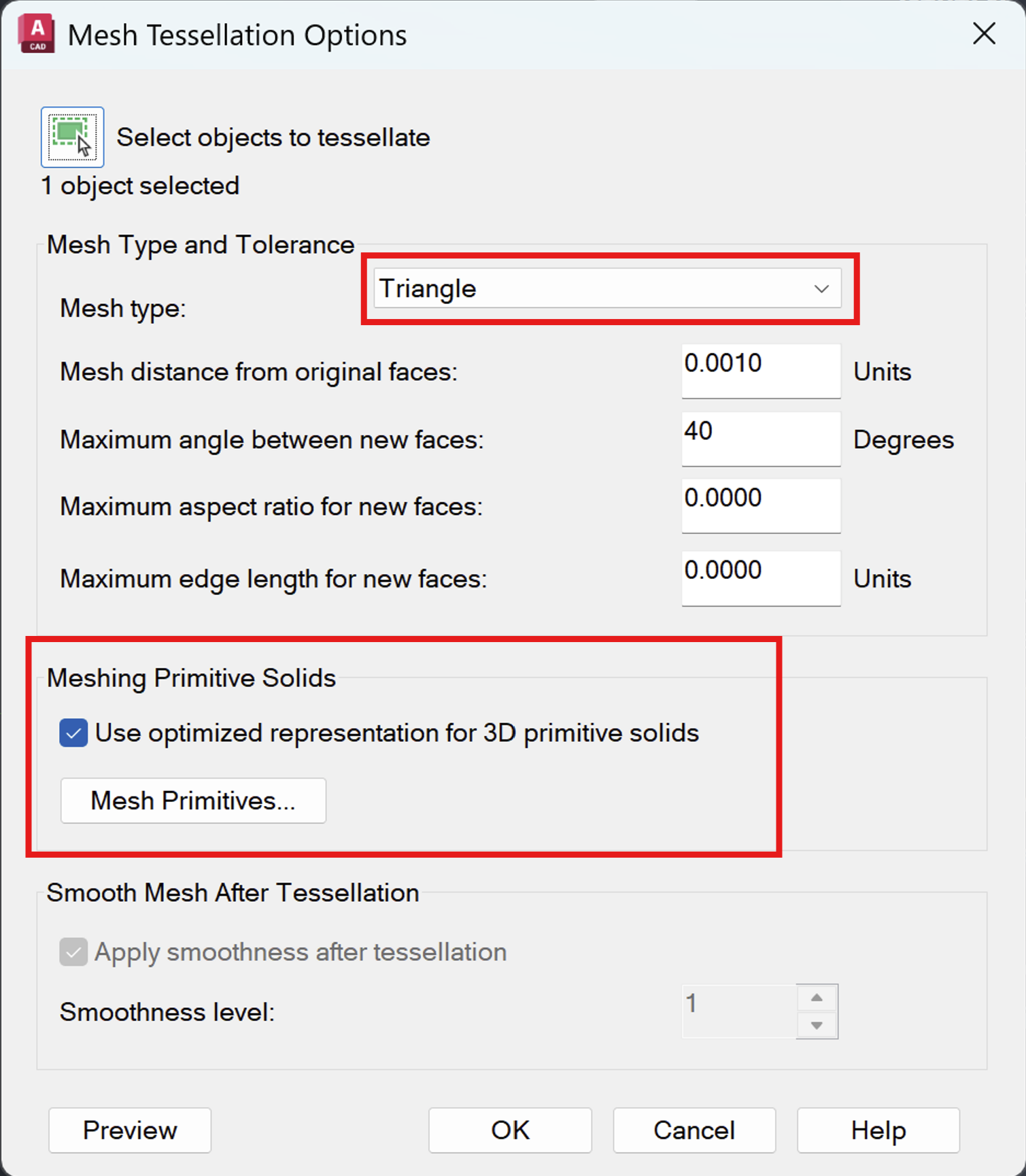
In this window, set the resolution of your mesh. Select Meshing Primitive Solids to optimize the meshing for primitives such as a cylinder. Select the mesh type Triangle, as shown in the picture below.
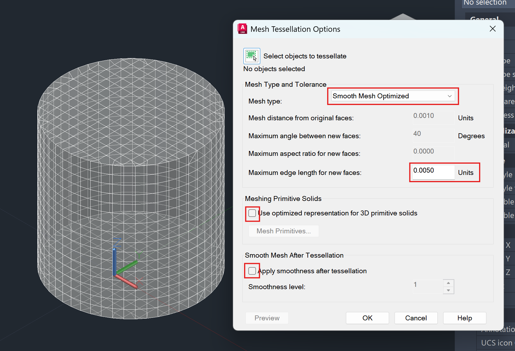
You can also edit the maximum edge length when generating new faces. This will attempt to create elements with boundaries smaller than the limit set. The picture below shows how setting a limit of 5 mm creates very small faces. In this case, deselect the Meshing Primitive Solids checkbox and the box that applies smoothing in the lower panel.
Import the DXF into the SDK
The final step consists of saving the geometry as a DXF file and importing it into the SDK.
Setup the device properties:
device_name = "SmartSpeaker"
device_model_path = "data/SmartSpeaker.dxf"
device_microphone_placements = [ # speaker microphones
    treble.Point3d(0.00,0.00,0.08),
    treble.Point3d(0.01,0.00,0.08),
    treble.Point3d(-0.01,0.00,0.08)
    ]

frequency = 12000
ambisonics_order = 32
freefield_model_name = "Smart_speaker_model"
freefield_simulation_name = "Smart_speaker_sim"
Prepare the free field simulation:
ff_def = p.setup_drtf_simulation(
    simulation_name=freefield_simulation_name,
    freefield_model_name=freefield_model_name,
    device_geometry=device_model_path,
    device_microphone_placements=device_microphone_placements,
    frequency=frequency,
    ambisonics_order=ambisonics_order,
)
ff_def.plot()
Add the free field definition and start the simulation:
ff_sim = p.add_simulation(ff_def)
ff_sim.start()
Add the device to the organization library:
results_dir = "your_path_here"
ff_res = ff_sim.get_results_object(results_directory=results_dir)

device_def = ff_res.create_drtf(device_name='smart_speaker_one', ambisonics_order=32)
device = tsdk.device_library.add_device(device_definition=device_def)

device.plot()
The speaker file exported from Autocad is made available as a .dxf file in the bundle below:
This guide has been tested with AutoCAD version 2026.