Exporting a geometry suitable for DRTF generation from Solidworks
Solidworks is one of the leading tools to design complete products as well as mechanical parts and assemblies. As such, it allows you to work on the geometry at maximum precision, keeping all the information in the same file.
To generate a DRTF, you currently need to create a version of the file consisting of a triangulated mesh geometry.
This tutorial covers the workflow to create the object, create a mesh feature, export as STL, and convert to OBJ or DXF. Direct STL import for DRTF generation will be supported in a future release.
Key steps:
Create the object
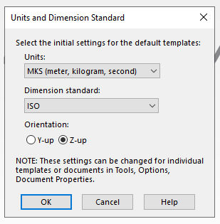
In Solidworks, start by setting the units to MKS Z-up to model the geometry in meters — the simulation conventions assume the Z coordinate is oriented upwards.
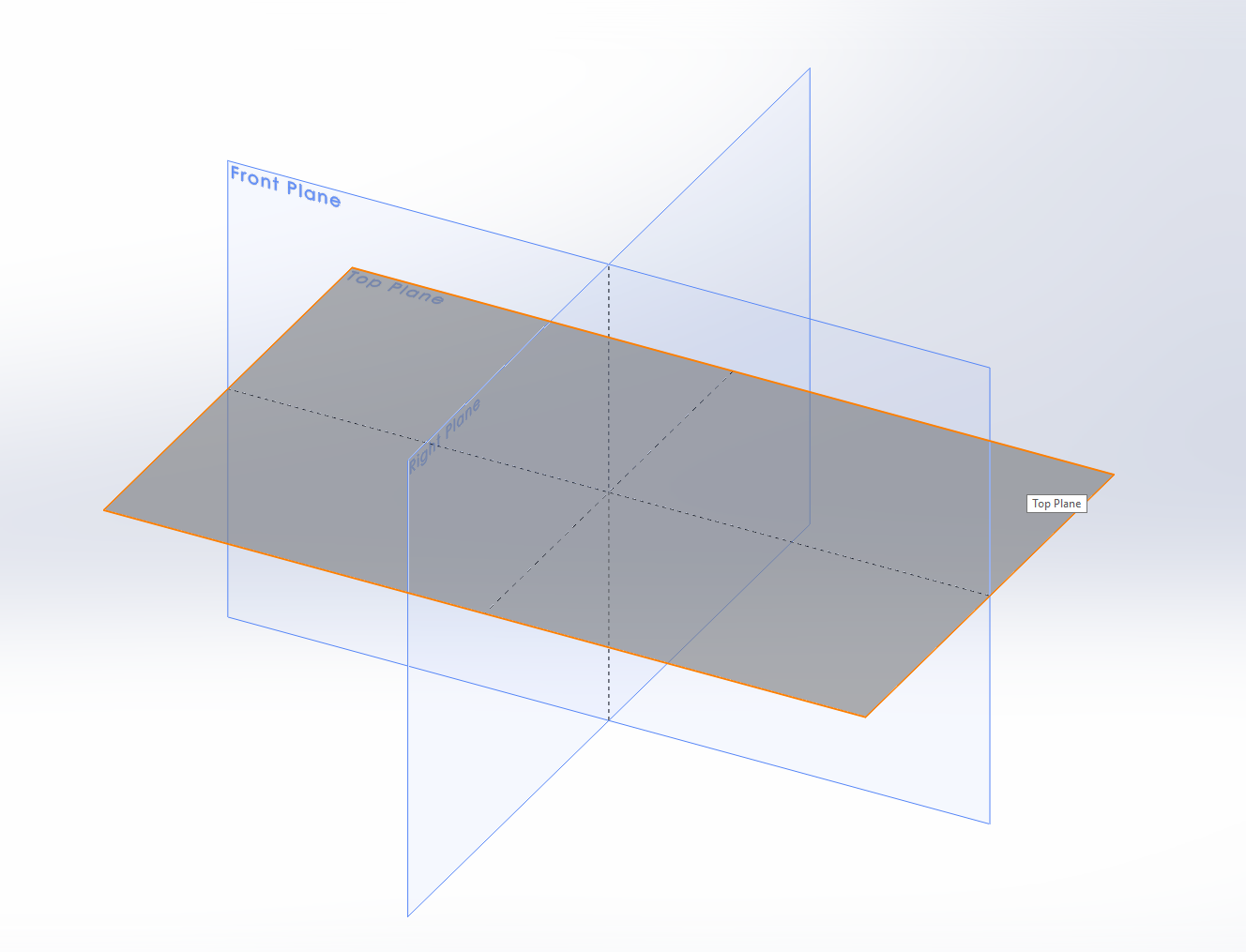
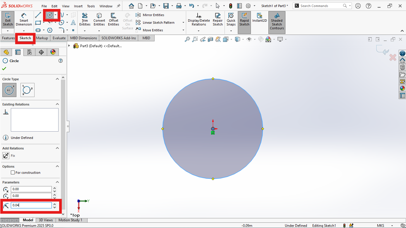
Use one of the Sketching tools such as Circle to define a generator geometry in the XY plane, which will be the base of the solid geometry.
Make sure the circle has its center at the origin and a radius of 4 cm (0.04 m), as shown in the inspector.
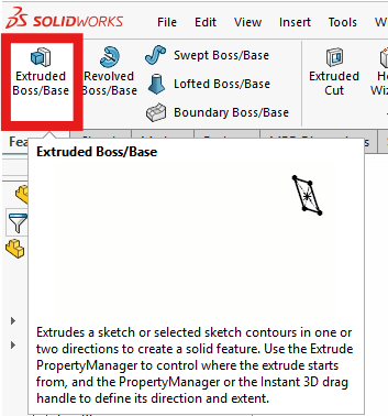
Proceed with the Extruded Boss/Base command in the Feature tab.
Set a direction, for example Blind, with a length of 0.1 m and a Draft angle of 4 degrees. Apply a length of 0.015 m and a Draft angle of 12 degrees to the bottom extrusion. Confirm with the green checkmark.
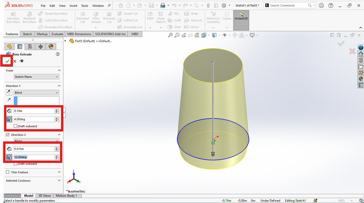
The image below shows the object with the parameters just set. Save the file and proceed with the next step.
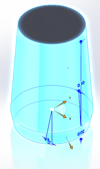
Create a mesh feature
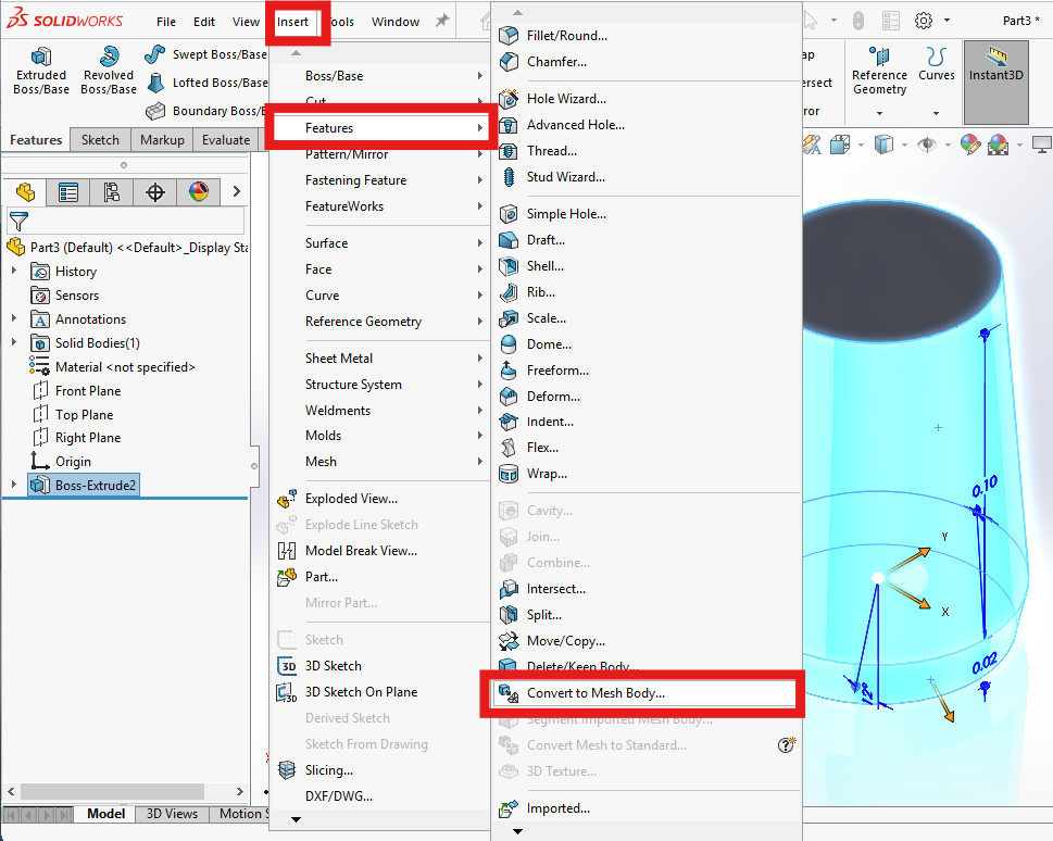
With all the object parts selected, navigate to Insert > Features > Convert to Mesh Body.
This opens a panel where you can select the body and choose whether to keep the original. For this example, assume you are working on a copy and don't keep the original. Choose the mesh refinement on a slider ranging from Coarse to Fine, or select Advanced Mesh Refinement Options.
For this example, we recommend setting the options to the Coarser settings.
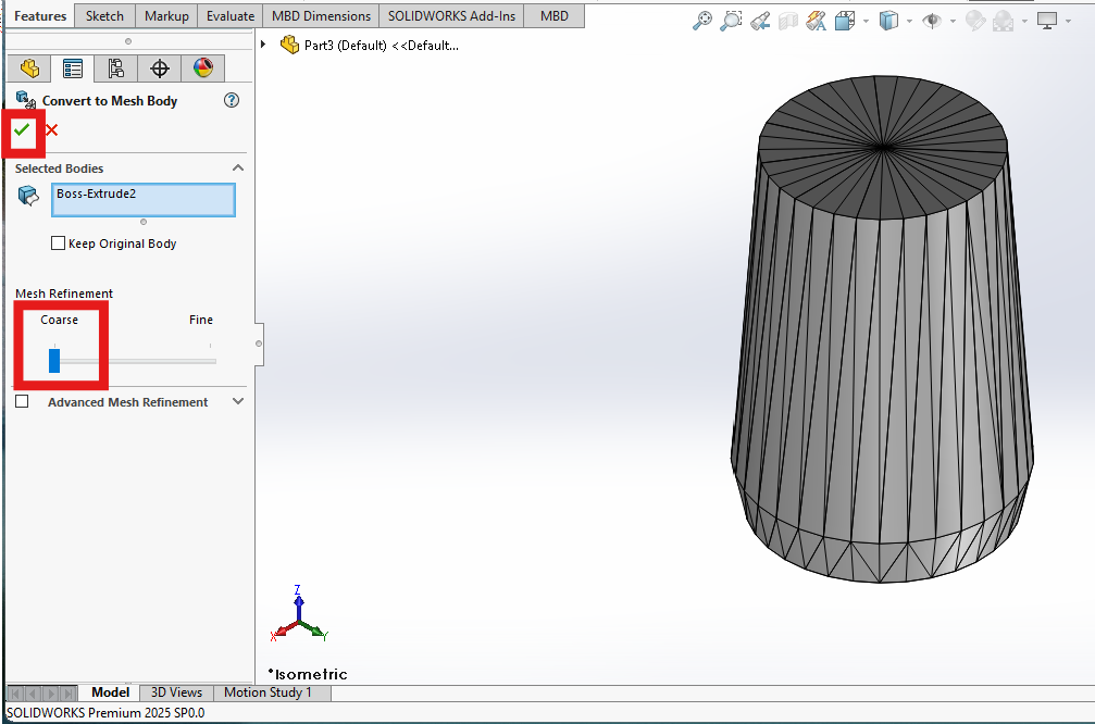
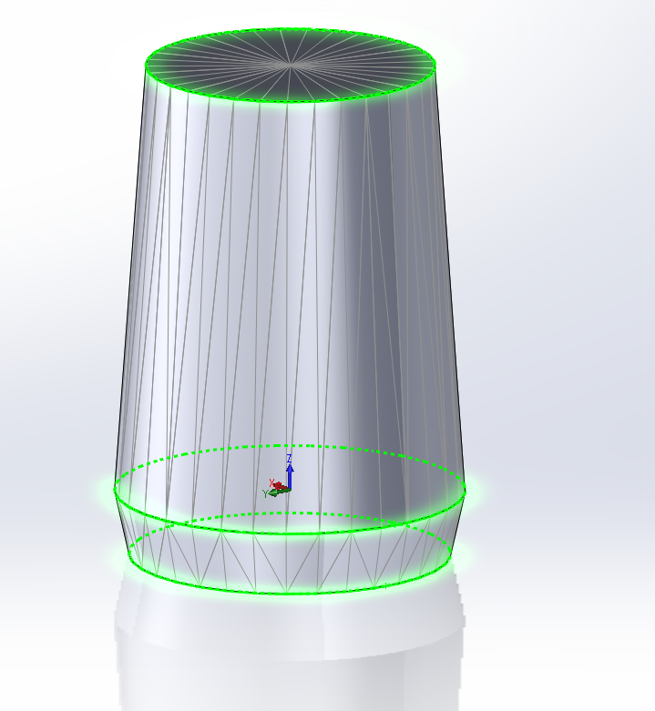
The object now appears made of triangles. It can be exported as STL.
Export as STL
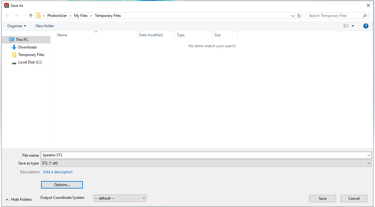
From File, click Save or Ctrl+S and select STL file format.
A window panel allows you to set additional export options. Check the parameter Do not translate STL output data to positive space, since this will otherwise move the object coordinates (this option can be handy when manufacturing).
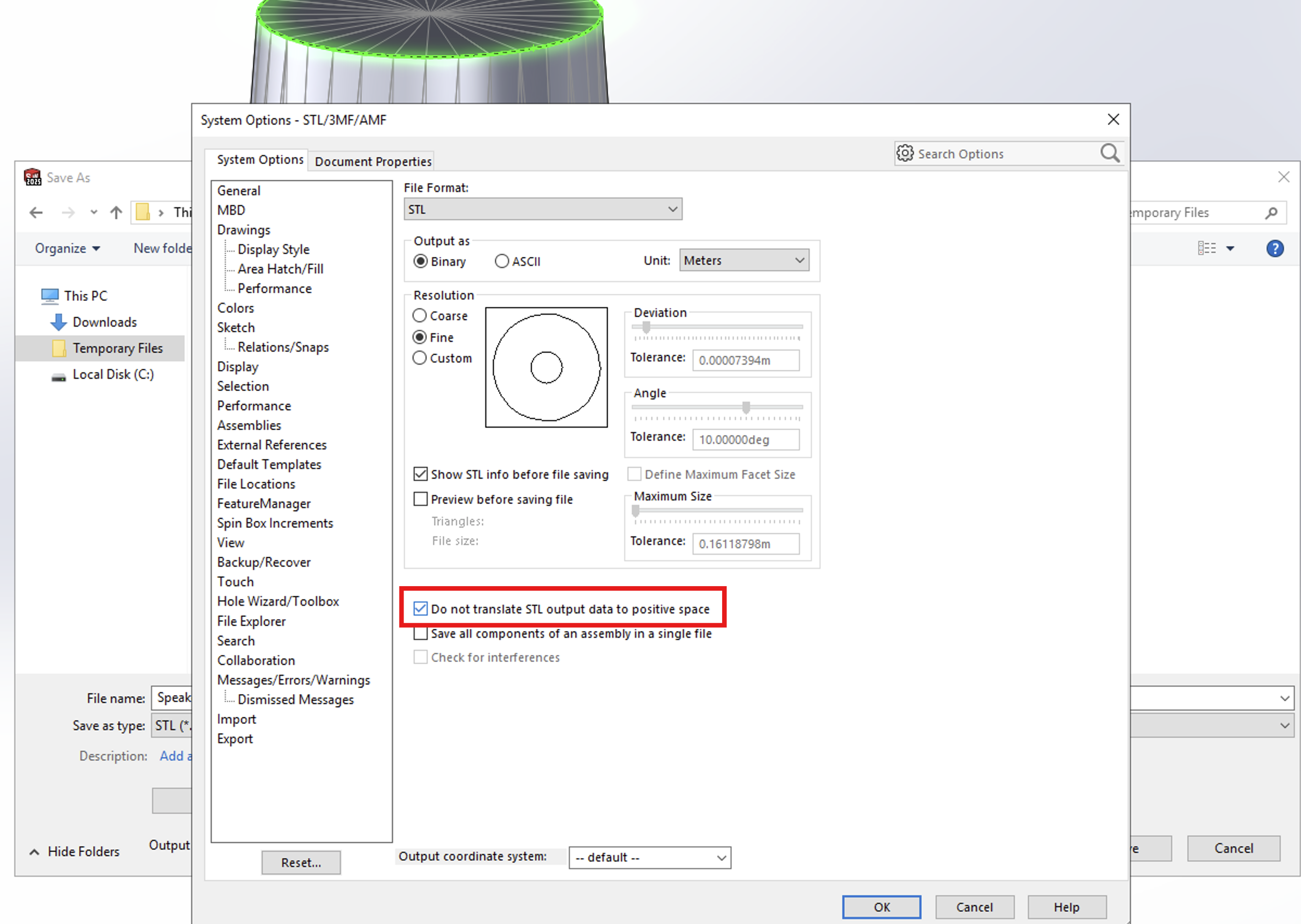
You can also control whether the object needs additional processing, in case it hasn't been previously meshed. Set the export options to Fine. Units must be in meters.
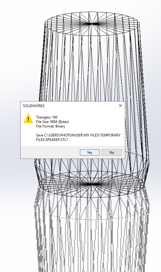
Convert from STL to DXF or OBJ
Once the STL file is saved, convert it to either DXF or OBJ.
If you have a native exporter for STL to OBJ, that is preferable. Otherwise, use an online conversion service such as Convert3D. The conversion from STL to OBJ has been tested with this tool.
Although Solidworks supports DXF export, this works only for 2D drawings and is not suitable for generating 3DFACE objects, which is what the Treble SDK requires when importing DXF files.
Direct STL import will be supported in a future release.
Import the OBJ into the SDK
If you converted the geometry into an OBJ file (or .DXF), import it into the SDK.
Setup the device properties:
from treble_tsdk import treble

tsdk = treble.TSDK()
project = tsdk.get_or_create_project("test-speaker")

device_name = "SmartSpeaker"
device_model_path = "Speaker_example.obj"
device_microphone_placements = [  # speaker microphones
    treble.Point3d(0.00, 0.00, 0.115),
    treble.Point3d(0.01, 0.00, 0.115),
    treble.Point3d(-0.01, 0.00, 0.115),
]

frequency = 12000
ambisonics_order = 32
freefield_model_name = "Smart_speaker_model"
freefield_simulation_name = "Smart_speaker_sim"
Prepare the free field simulation:
ff_def = project.setup_drtf_simulation(
    simulation_name=freefield_simulation_name,
    freefield_model_name=freefield_model_name,
    device_geometry=device_model_path,
    device_microphone_placements=device_microphone_placements,
    frequency=frequency,
    ambisonics_order=ambisonics_order,
)
ff_def.plot()
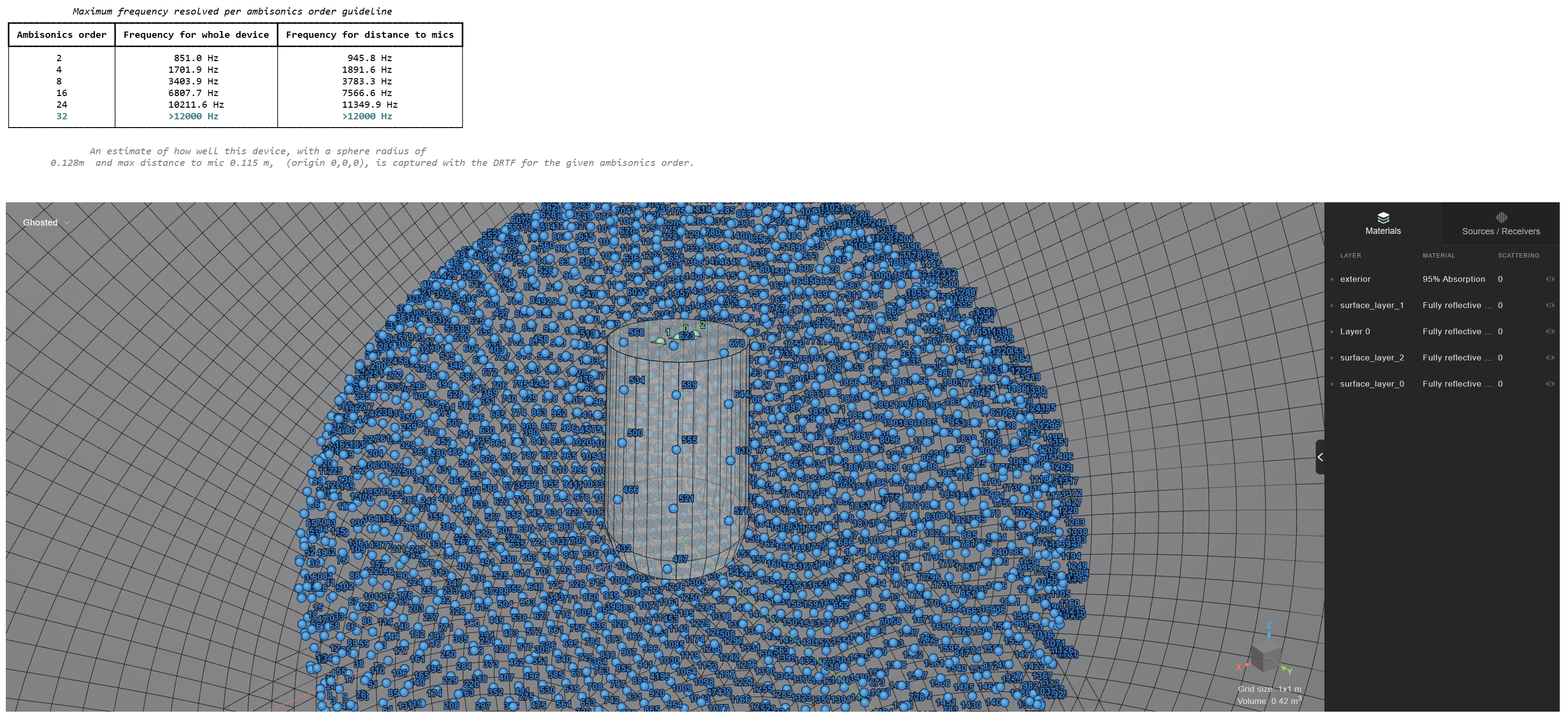
This free field simulation would work better if the speaker was placed in the center of the free field. You can do so in your modelling tool or in the SDK by using the GeometryComponentGenerator.
Add the model to the project and transform it into a component.
from treble_tsdk.geometry.generator import GeometryComponentGenerator

speaker = project.add_model(
   model_name="Smart_Speaker",
   model_file_path="Speaker_example.obj"
)
speaker.wait_for_model_processing()

vector = treble.Vector3d(0, 0, -0.05)
rotation = treble.Rotation(0, 0, 0)
transform = treble.Transform3d(vector, rotation)

gc = GeometryComponentGenerator.create_component_from_model(speaker,component_name="my_translated_speaker",transform=transform)
Define the path to the imported component and the translated microphone coordinates
device_name = "SmartSpeaker_centered"
device_model_path = gc # the imported components
device_microphone_placements = [ # translated microphone coordinates
    treble.Point3d(0.00,0.00,0.065),
    treble.Point3d(0.01,0.00,0.065),
    treble.Point3d(-0.01,0.00,0.065)
    ]

frequency = 12000
ambisonics_order = 32
freefield_model_name = "Smart_speaker_model_centered"
freefield_simulation_name = "Smart_speaker_sim"

ff_def = project.setup_drtf_simulation(
    simulation_name=freefield_simulation_name,
    freefield_model_name=freefield_model_name,
    device_geometry=device_model_path,
    device_microphone_placements=device_microphone_placements,
    frequency=frequency,
    ambisonics_order=ambisonics_order,
)
ff_def.plot()
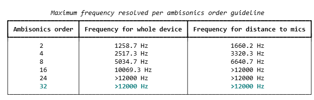
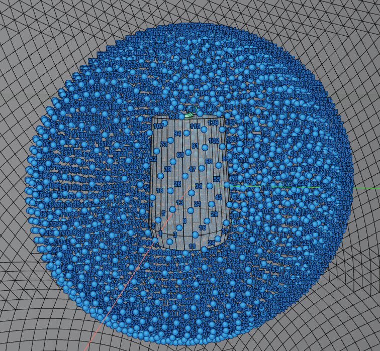
The speaker is now centered in the free field domain. Notice that the ambisonic order you need to cover the distance to the microphone is now 16, while in the previous example it was 32.
Add the free field definition and start the simulation:
ff_sim = project.add_simulation(ff_def)
ff_sim.start()
Add the device to the organization library:
results_dir = "your_path_here"
ff_res = ff_sim.get_results_object(results_directory=results_dir)

device_def = ff_res.create_drtf(device_name="smart_speaker_one", ambisonics_order=32)
device = tsdk.device_library.add_device(device_definition=device_def)

device.plot()
The speaker file exported from Solidworks is made available as an .obj file in the archive below:
This guide has been tested with Solidworks 3DExperience