Geometry feedback
Making sure that importing geometries is as forgiving yet reliable as possible is one of the core goals of the Treble suite.
Our plugin comes with a feedback tool that will help you taking care of potential issues early in the preparation process. Here is a detailed explanation of what each of the type of errors and warnings mean, and how to fix them.
Only the errors will prevent you from uploading your model, warnings are just here to flag potential problems. In the near future, it will be possible to upload non-watertight geometries to be used with the Geometrical Acoustics solver.
Errors
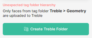
Unexpected tag folder hierarchy
Why
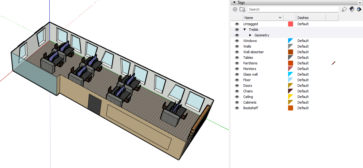
Treble has its own tag folder in which it will pick the entities to include in the analysis. This allows you to easily add and remove entities from the model that you want to analyse, without having to remove anything.
Probable causes
> Geometry tag folder dragged out
When dragging a tag, SketchUp 21 and SketchUp 22 drag the selected tag, regardless of which tag has been clicked. It is quite easy to mistakenly remove the tag folder Geometry from the tag folder Treble.
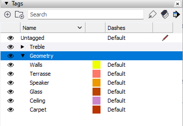
Fix: Drag the tag folder Geometry back to the tag folder Treble
> Model is new or newly imported
Fix: Click on the button Create Treble Folder
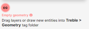
Empty geometry (EG)
Why
No entities could be found in the Treble Geometry tag folder.
Probable causes
> Newly imported document
Fix: If you imported a document to SketchUp, you will have to drag the layers that you want to include in the simuation into the Treble Geometry tag folder.
Warnings
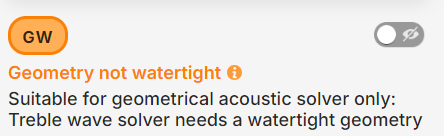
Geometry not watertight (GW)
Why
At the moment, models must have a watertight outer shell in order for Treble wave-based simulation to run.
Without one, the model can only be uploaded for ray-tracing analysis, provided that there are no wide gaping holes that would let too much energy out (see Partly successful checks > Upload for ray-tracing only).
Feedback toggle
The feedback toggle shows you the open edges that are likely to be holes in the geometry (if any found).
Probable causes
> Untagged faces
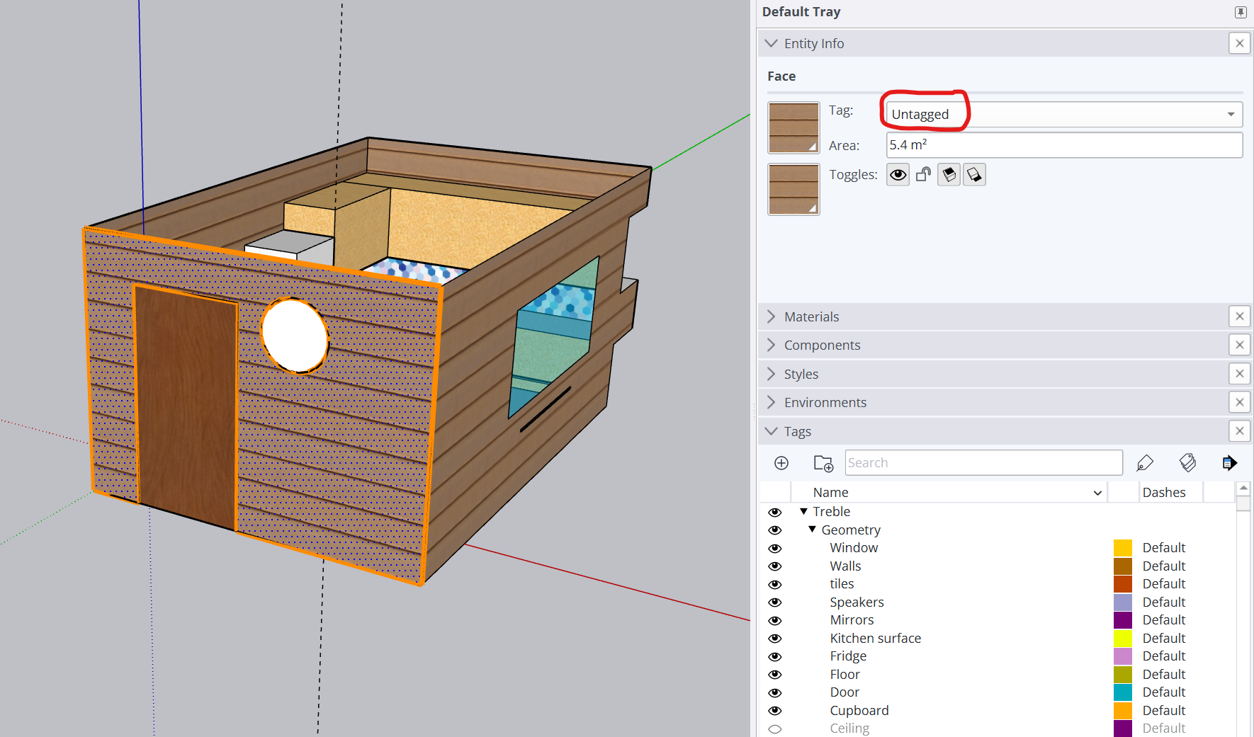
In this example, the selected wall has not been tagged, which causes it to be excluded and makes the geometry non-watertight.
A face having all its edges highlighted in orange is most often a symptom of a missing tag in the case of a GW warning.
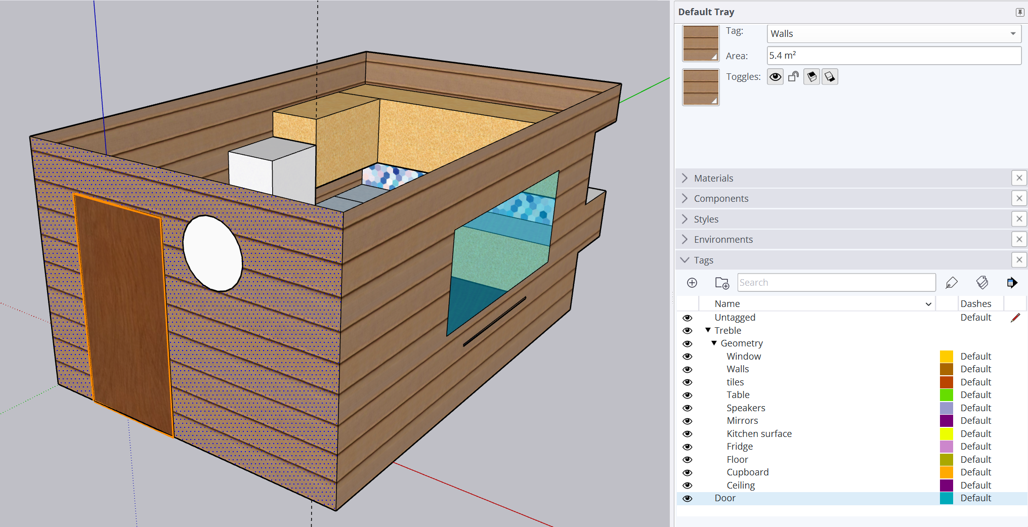
Fix: Tag the face with the desired tag - here, set the tag Walls.
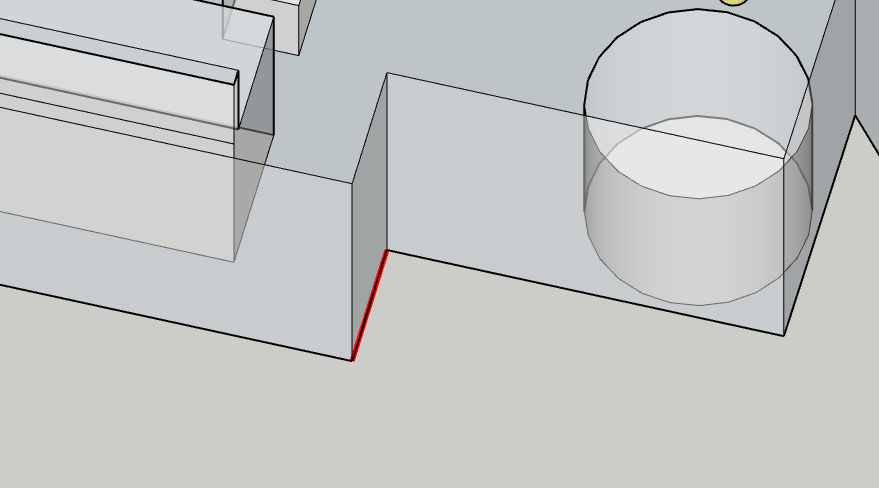
> Excluded tag
In this example, the tag Doors is not included in the Treble Geometry tag folder, and this causes the outer shell to be open where the orange lines are displayed.
Fix: Select the tag and drag it in the Geometry tag folder.
> Gap between faces
In this example, importing the file into SketchUp left a very small gap that is not directly visible in Sketchup. After zooming in enough, the problem becomes more obvious.
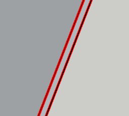
Fix:
- select one edge and move it above the other, to merge them together
- or redraw the face without the gap
Exclusions (EX)
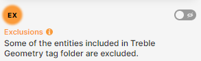
Why
The simulation can only run within the watertight outer shell of the geometry. This is a warning that some of the geometry of the Geometry tag folder will not be included in the simulation.
Feedback toggle
The feedback toggle shows you the faces of the Geometry tag folder that will be excluded from the simulation.
Probable causes
> Some faces are outside of the outer shell
Any object that is outside the outer shell will be excluded, even if it is included in the Geometry tag folder.

In this example, the layers Terrace and Fence are excluded.
Fix: If the faces are not meant to be in the simulation, remove their layer from the Geometry folder, or move the faces into a different layer.
If the faces are meant to be in the simulation, move them inside the outer shell.
Note: Sometimes faces that are only partly outside of the outer shell are still excluded, but we are currently refining our detection algorithm to prevent such exclusions.
> A component is fully overlapping with an outer shell face
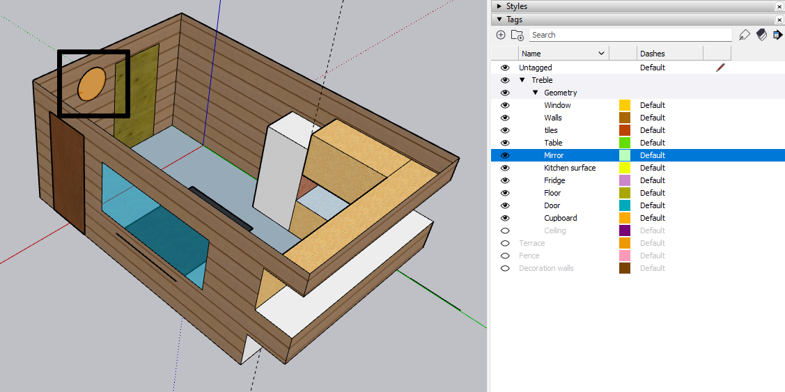
If you place a component that exactly overlaps with an outer shell face, it might be excluded; here the mirror on the wall is highlighted in orange. (We are working on making the face overlap detection algorithm more robust.)
Fix: Make a hole for the component in the outer shell face.
To do so:
- Right click on the component
- select Intersect Faces > With model
- Hide the layer in which the component is
- Delete the new inner face matching the component that got created in the outer shell
- Unhide the component
Information
Isolated edges (IE)
Why
Isolated edges are Open edges that are likely to be symptoms of a hole in a group of faces.
They can be ignored if the geometry is watertight (no GW warning or BM warning) but keep in mind that a hole might be showing that some faces are missing in Treble > Geometry tag folder.
Probable causes
Open edges (OE)
Why
Open edges warning appears when the geometry has no watertight outer shell and but are not as isolated as the Isolated edges; they might be the outside edge of the surface describing a table for instance, and thus are not necessarily something to fix.
They will be displayed alongside a GW warning or a BW warning.
Probable causes
Short edges (SE) and small gaps (SG)
Why
The wave-based simulation speed is inversely related to the size of the smallest "air" element in the geometry.
That means that if your geometry has one very small edge or a small gap between elements, the wave-based simulation will be slower than it could be.
A table with the relevance of details can be found here.
The analysis reports what seems too small in the default transition frequency, which is calculated according to the volume of the model. Thus the warnings should be taken with a pinch of salt, especially if you do not use the default transition frequency in the web app:
- if you use a higher transition frequency, the warnings can be a bit too sensitive.
- if you use a lower transition frequency, you might have unreported edges or gaps causing noticeable slowdown.
Probable causes
> Small edges in thin objects (table, chair, screens, etc.)
It is best to replace thin volumes with a flat, open surface: open surfaces are much faster to process:
A rule of thumb is that anything with a thickness that is less than 5cm ought to be replaced with a flat surface, as the thickness of it has a negligible value in the simulation (any model object smaller than 1/4 of the wavelength can be removed) - see detail relevance table.
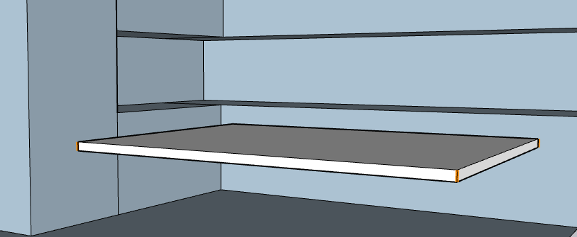
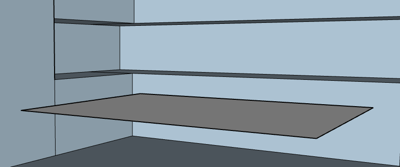
> Small gaps between objects
Sometimes objects might be really close to each other, which would generate poor 3D elements for the wave-based solver. This can negatively impact on the performance of the simulation time quite a lot.
In the screenshot below you can see that the checking service returned a list of small gaps:
When the gap between the elements is indeed very small, it is best to collapse the elements into one as the air gap will not impact the wave propagation anyway (see the detail relevance table on that matter).
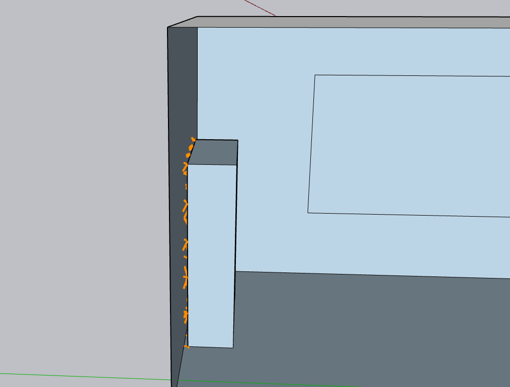
In our example, the distance between the wall and the object is indeed very small: 0.03m. This is not even relevant when setting the transition frequency 2kHz:
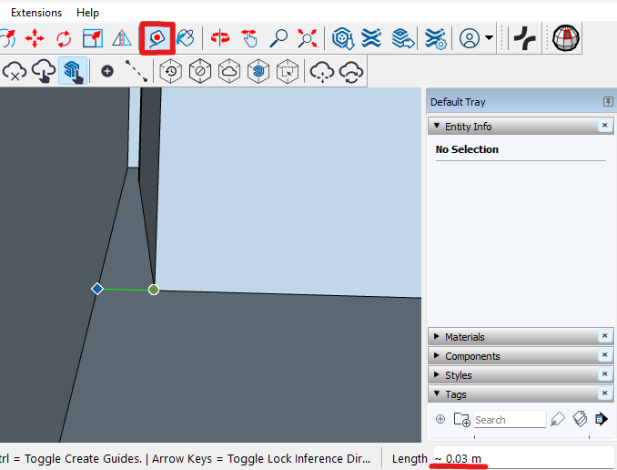
Fix: The solution here is to use the Push/Pull tool and drag the object's face onto the wall:
> Curves
SketchUp defines curves (such as circles or cylinders) with a polygon with 24 edges by default. This might lead to problematically small edges in the Geometry analysis, but our wave-based solver will simplify them according to the transition frequency.
Fix: Amending the geometry for curves is not really necessary in SketchUp, unless unreasonably long simulation times occur. In such case, sending us feedback on the problematic model will help in coping with uncommon model configurations.
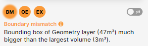
Boundary mismatch (BM)
Why
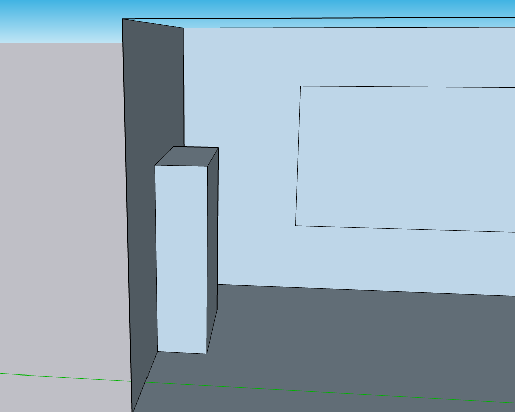
Our detection algorithm defines the largest watertight volume of the geometry as the outer shell in which the simulation will take place. If the space you want to simulate on has a hole and there is an inner volume in it, then this inner volume will be seen as the outer shell for the simulation.
The boundary mismatch comes here as a warning that the bounding box of the model is at least 4 times bigger than the bounding box of the biggest watertight solid of the geometry, to help you spotting a potential error before uploading the model.
This warning will most likely come with exclusion (EX) and open edges (IE / OE) warnings, as a report of the entities outside of the smaller watertight volume and of the hole triggering such a state.
Probable causes
Known issues
Automatic preparation and import of geometry is obviously a complex skill that we are constantly honing.
Our Trebleshooting page contains more information about known issues and issues that are not displayed by the feedback.
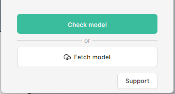
Any feedback related to the feedback feature can be reported using the Support button in the tool.