Import a device with the widget
The device import widget is a graphical user interface that opens in your notebook. With it you can import a device, put it on a mannequin, check the geometry and add it to your project without writing code. This page goes through every part of the widget. For a walk-through from CAD to simulation, see Smart glasses on a mannequin.
Open the widget
Run this in a notebook cell:
from treble_tsdk import treble
from treble_tsdk.device import start_device_model_import

tsdk = treble.TSDK()
project = tsdk.get_or_create_project(name="<project_name>")
start_device_model_import(project)
The side panel has two tabs at the top:
- Editor: import your model and set it up.
- Checks: see the results of your geometry checks. This tab opens after your first check.
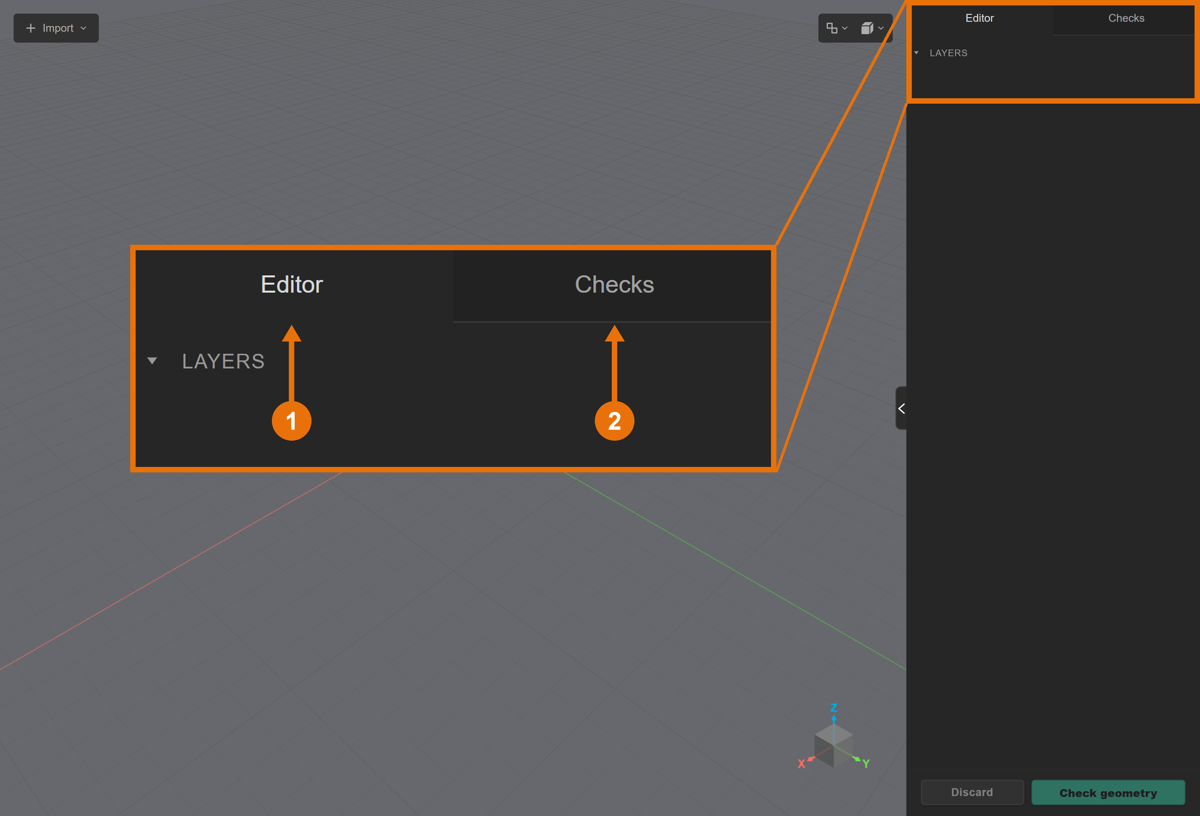
Set up your model in the editor
Import a device file
-
Click Import, then Import file, and pick your file.
-
For a CAD file (
.step,.stp,.iges,.igs), pick the Triangulation in the window that opens and click Parse CAD. Medium works for most devices. The file is then triangulated, which can take a moment for a big file.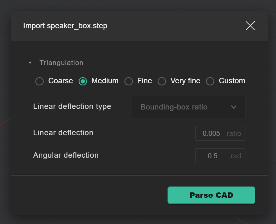
-
Check the import options in the window that opens (see below). It's the same for every file type.
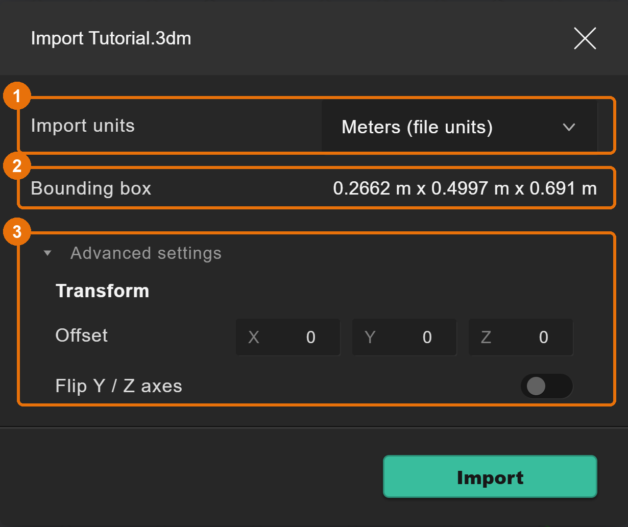
-
Click Import. The file shows up as an assembly in the side panel.
| Option | What to do | |
|---|---|---|
| 1 | Import units | Pick the units of your file. By default it uses the units stored in the file, or meters |
| 2 | Bounding box | Check the size. If it's far too big or too small, the units are wrong |
| 3 | Advanced settings | Offset moves the model. Flip Y / Z axes fixes a model lying on its side, common for OBJ |
Meshes: .3dm, .obj, .ply, .stl.
CAD: .step, .stp, .iges, .igs.
Add a mannequin
Click Import, then Import mannequin to open the mannequin import window. The mannequin library describes the heads and their variations.
Move and rotate a part
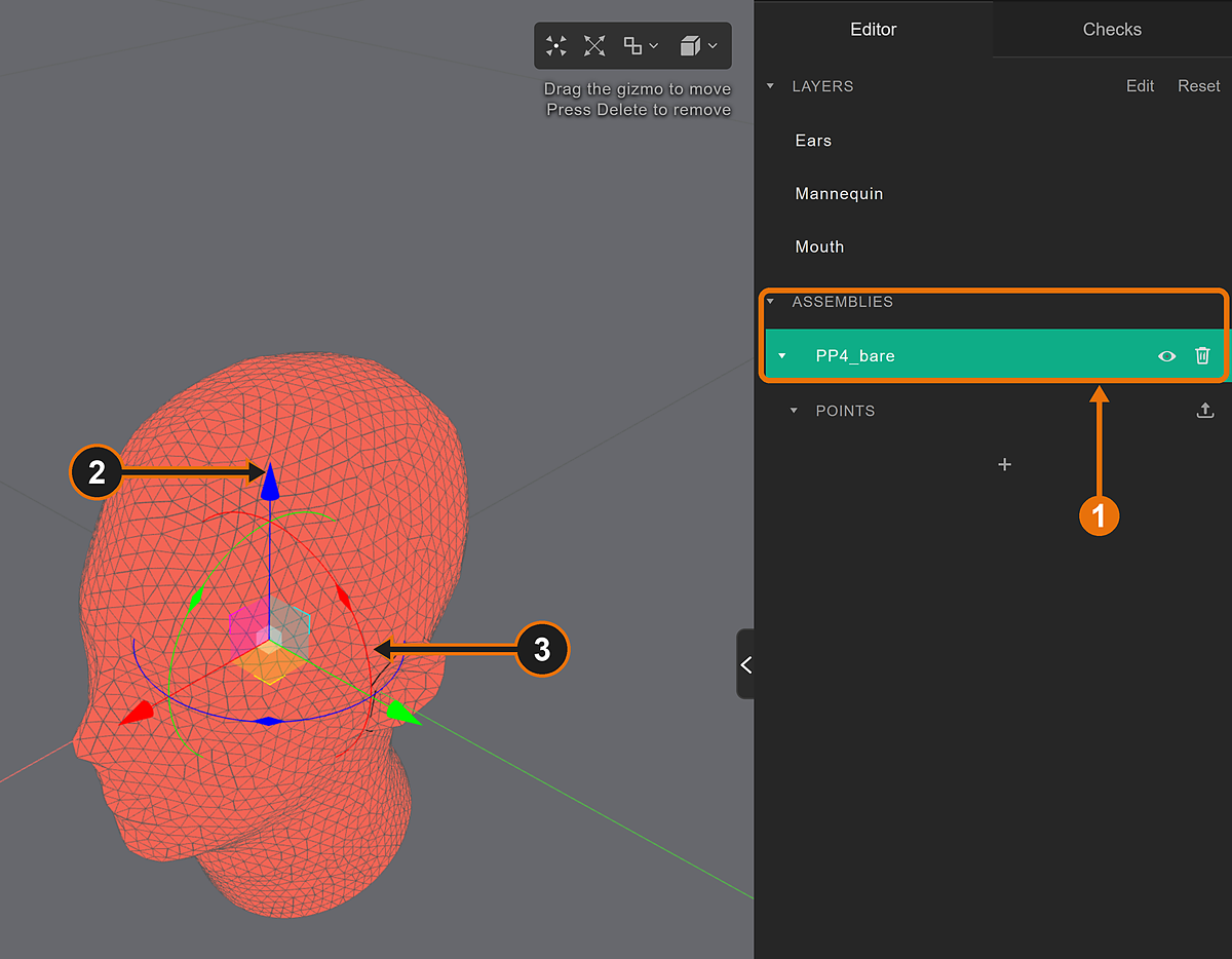
- Click the assembly in the side panel (1) to select all its parts. Hold Ctrl to select more.
- Drag an arrow of the gizmo (2) to move the selection along that axis.
- Drag a ring of the gizmo (3) to rotate the selection about that axis, around its center.
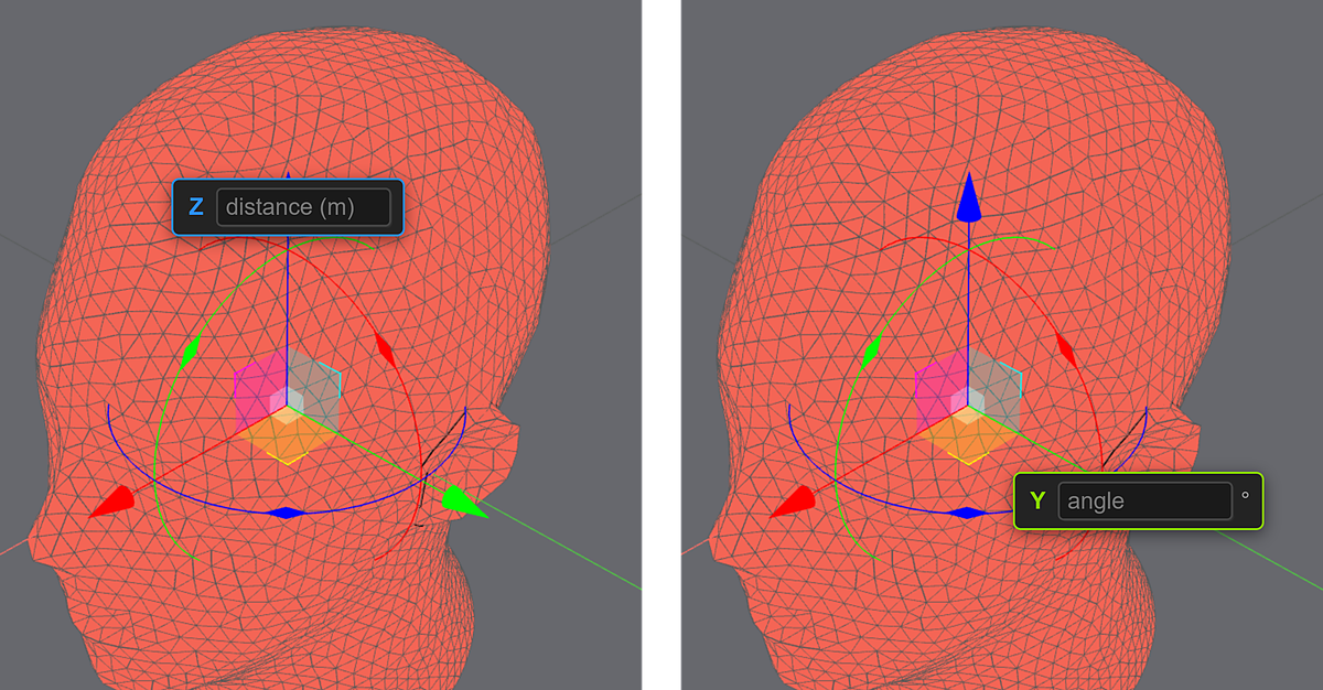
For an exact value, click an arrow or ring without dragging. Type a distance in meters or an angle in degrees, then press Enter, or Esc to cancel.
An arrow asks for a distance (left) and a ring for an angle (right):
| Shortcut | What it does |
|---|---|
| Ctrl+Z / Ctrl+Y | Undo / redo a move |
| Delete | Remove the selection |
Change the view and selection mode
The buttons at the top right of the 3D view change how you see and select the model.
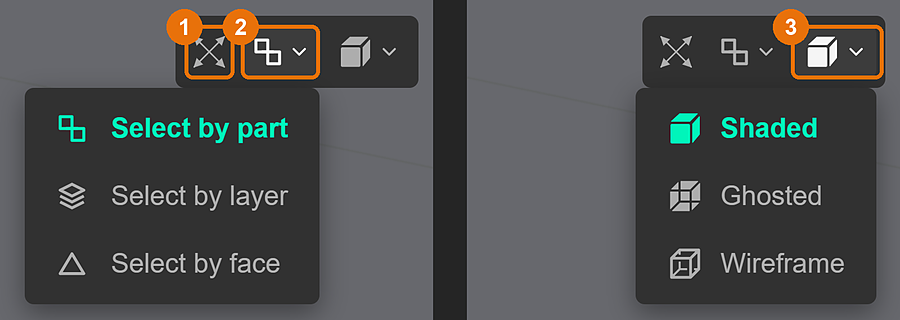
- Reset camera (1): back to an isometric view of the whole model. When something is selected, a Zoom to selection button shows up next to it.
- Selection mode (2): select by part, by layer or by face.
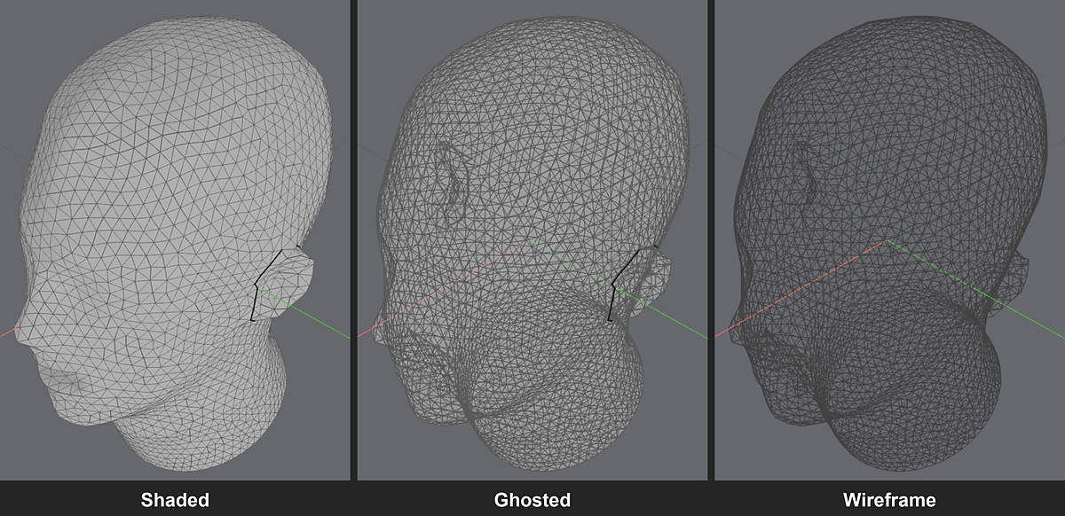
- View type (3): Shaded, Ghosted or Wireframe. Ghosted and Wireframe let you see parts inside or behind others.
Add points to assemblies
Points mark positions on an assembly, like your device. They belong to the assembly and keep their place on it when you move it, for example when you put your device on a mannequin. You can later get the coordinates of the points to use them as microphone positions when you define the simulation. Each assembly has its own Points list.
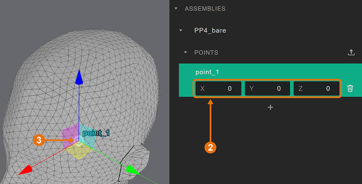
Add a single point
-
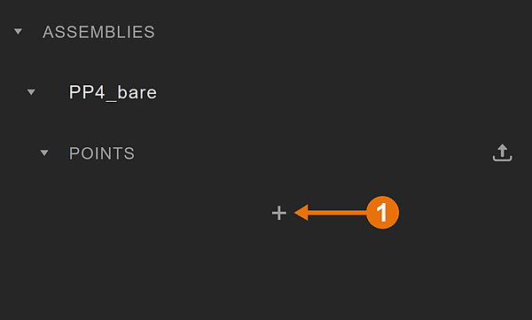
Click + under Points (1) to add a point at the origin.
-
Type its
X,YandZpositions in meters (2). -
Or drag the point to its place in the 3D view (3).
Add many points from a file
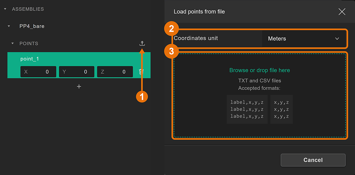
- Click the upload icon (1).
- Pick the Coordinates unit of your file (2).
- Browse to or drop a
.csvor.txtfile (3).
In the file, separate the values with commas, semicolons or tabs, and use a point as the decimal sign. In labels, every character that isn't a letter, a digit, - or _ is removed, and duplicate labels are made unique: two points labelled ear become ear and ear_1.
Use the points in Python
After you add the model to the project, you can get the points in Python to define the microphone positions in the simulation settings:
device_model = project.get_model_by_name("<model_name>")
print(device_model.points)  # {"point_1": [x, y, z], ...}
mic = device_model.point_as_device_microphone_info("point_1")
Show and hide layers
The Layers list shows the layers of all imported files.
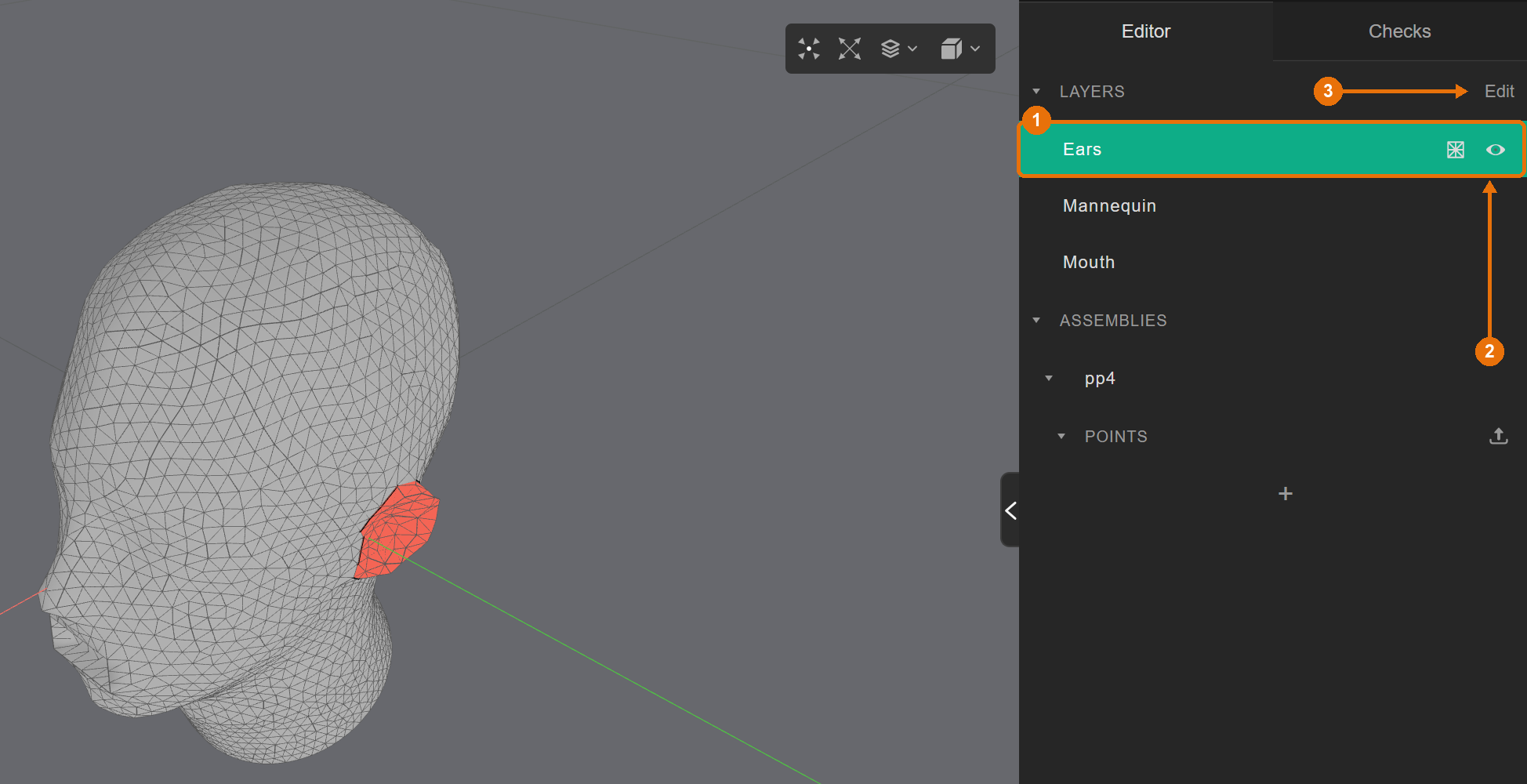
- Click a layer (1) to see it in red in the 3D view.
- The eye icon (2) hides or shows the layer.
- Edit (3) opens the edit mode, see below.
Layer editing mode
The edit mode lets you rename layers and change the layer of selected faces. Click Edit to open it. To rename a layer, click it, then click its name. Layer names must be unique, or the check won't start.
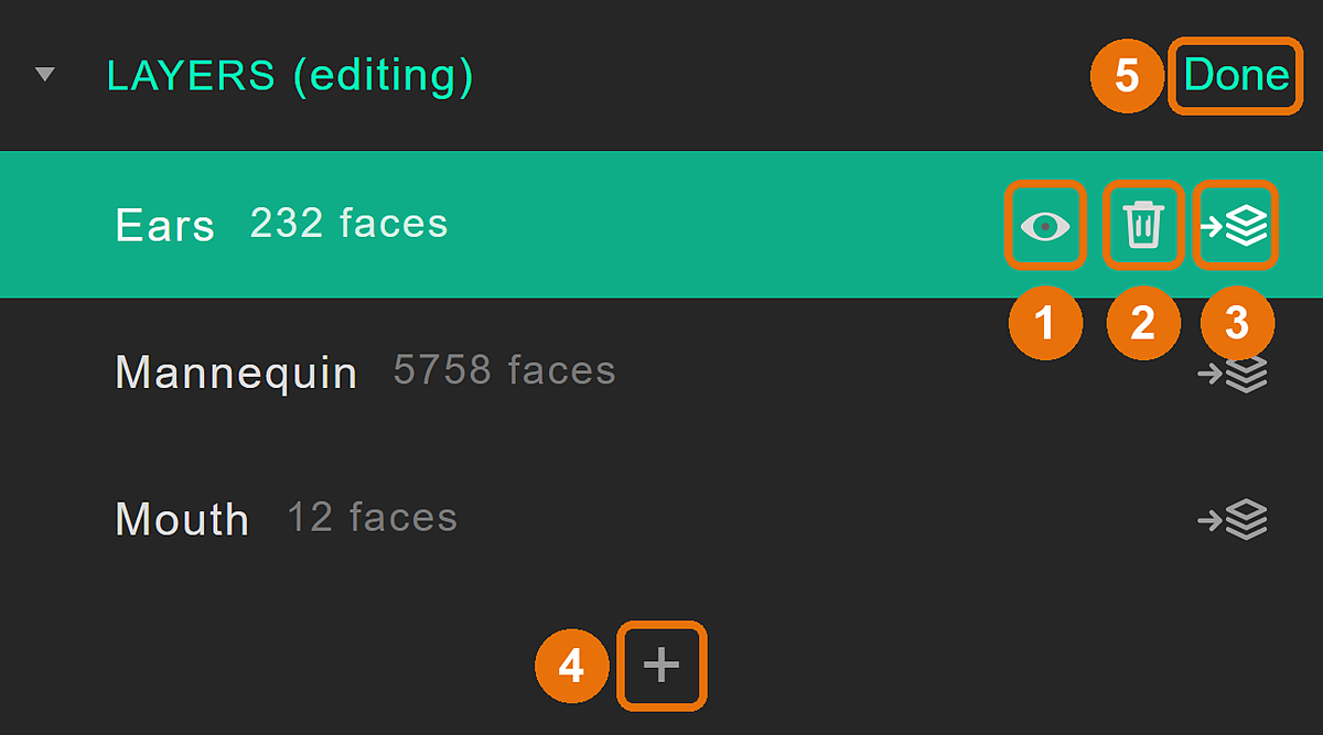
- The eye icon (1) hides or shows the layer.
- The bin (2) deletes it.
- To move faces to another layer, select them in the 3D view first (selection mode Select by face), then click the move icon (3) on the layer they should go to.
- Click + (4) to add a new layer.
- Click Done (5) when you're finished.
Set local sizing
Use local sizing to set sizing rules for one layer only. It's made for keeping speaker membranes and drivers, and for small wearable devices like glasses it rarely improves the quality.
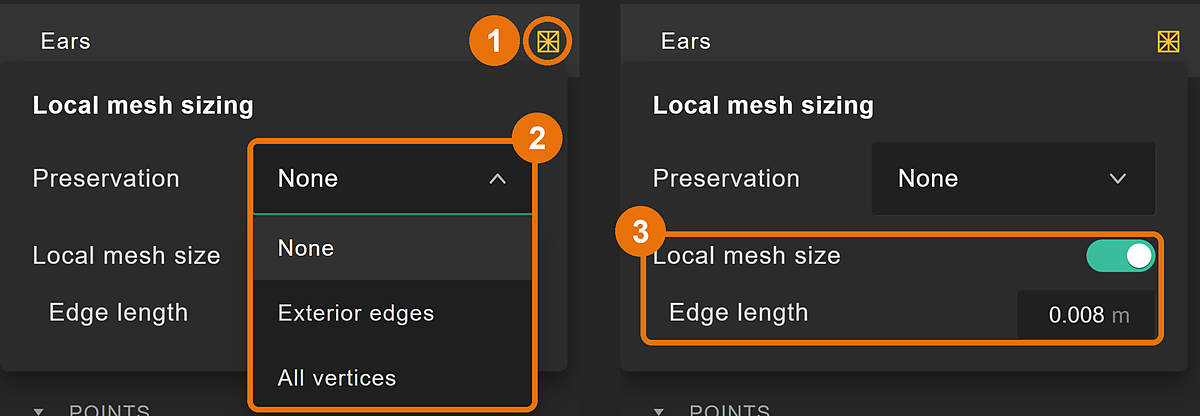
- Click the mesh icon on a layer (1) to open Local mesh sizing for it.
- Preservation (2): None lets the mesher simplify the layer like the rest. Exterior edges keeps the outline where the layer meets other layers. All vertices keeps curved shapes, but is likely to prevent sensible simplification and so make the simulation slower.
- Local mesh size (3): turn it on to set an Edge length in meters for this layer only, 0.008 m by default.
Local sizing helps in two cases:
- A finer size on a small driver, like a tweeter, can raise the mesh quality. On a two-way test speaker, 5 mm on the driver layers took it from 12.1 % to 19.6 %.
- A coarser size on big, smooth parts, like a cabinet, a torso or the mannequin, gives far fewer elements at the same mesh quality. For glasses on a head, 12 mm on the Mannequin layer halved the number of elements and left the glasses as they were.
Check the geometry
Once your device is ready, check the geometry to prepare the model and get feedback on its quality.
- Click Check geometry at the bottom of the side panel.
- Check the settings (see below).
- Click Run check. The check runs in the cloud and can take a few minutes.
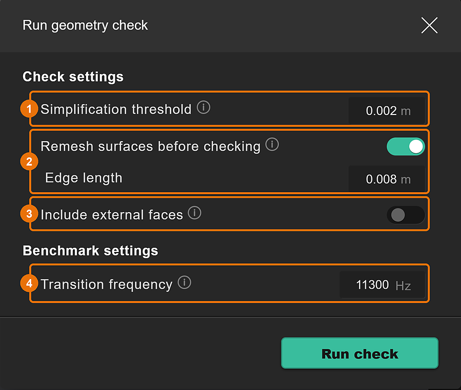
| Setting | Default | What it does | |
|---|---|---|---|
| 1 | Simplification threshold | 0.002 m | Edges shorter than this can be simplified away |
| 2 | Remesh surfaces before checking | 0.008 m | Remeshes the surfaces to an even Edge length first, which can help with small or irregular triangles |
| 3 | Include external faces | Off | Use it if your device has flat, external surfaces that are dropped without it |
| 4 | Transition frequency | 11300 Hz | The frequency the geometry is prepared and benchmarked for |
- Mannequins from the library are built for the default settings. Keep them as they are.
- For your own device, start with the defaults and use Check sent model again to compare other settings. A larger simplification threshold raises the quality but distorts the geometry more. Turning on or changing the remesh size helps with irregular device meshes.
- Don't remesh finer than about 6 mm. A finer mesh is slower to check and doesn't necessarily raise the quality.
- Keep the simplification threshold at 3 mm or less. Larger values can simplify away small parts of the device and distort the geometry too much.
- Include external faces only matters for open parts outside the closed shell, like a thin flap. Turn it on if parts you need are listed under Extra faces.
Review the check results
The result of a check opens in Checks.
Read a check result
-
The details of the result open when you switch to Checks.
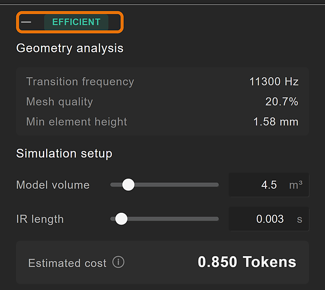
- Geometry analysis:
- Transition frequency: the transition frequency you picked for the check.
- Mesh quality: the quality of the 3D mesh compared with a perfectly even 3D mesh. The higher it is, the more efficient the simulation.
- Min element height: the size of the smallest element in the 3D mesh.
- Simulation setup: the Model volume and IR length used for the cost estimate. At a transition frequency of 8000 Hz or more they default to 4.5 m³ and 0.003 s, the DRTF sphere of a device simulation. Below that, they default to 50 m³ and 0.4 s, a small room.
- Estimated cost: the tokens for one source and one receiver. See the token estimator.
- Geometry analysis:
-
Above the result, the sections show what the check ran with and found:
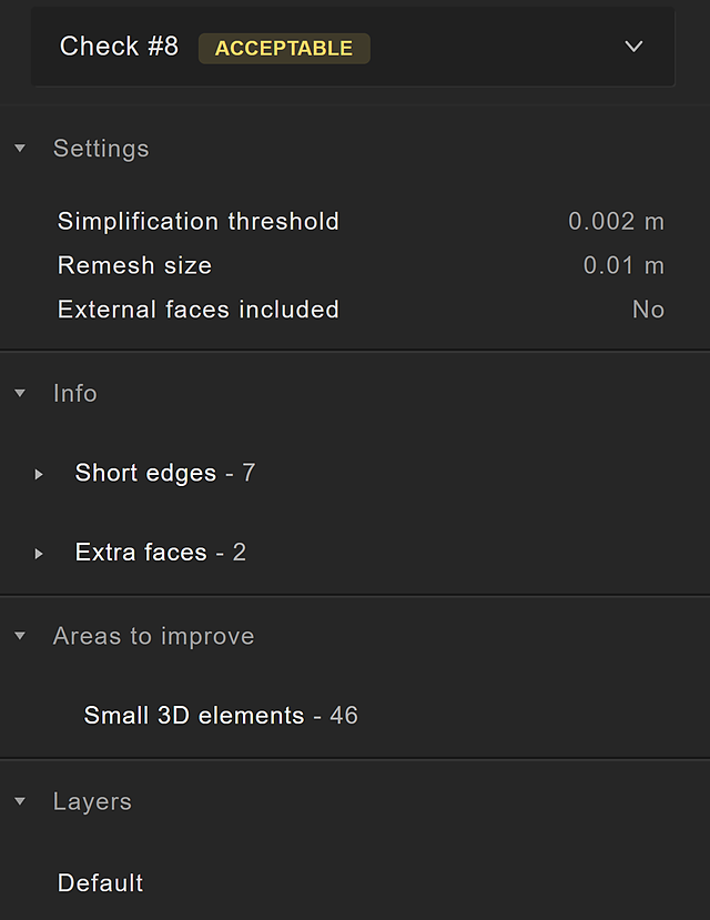
- Settings: the settings the check ran with.
- Errors: only there if the check failed, with what went wrong.
- Info: notes about the model, like Excluded faces, Short edges and Extra faces that were left out. Click one to highlight it in the model.
- Areas to improve: the spots with the smallest elements (Small 3D elements), which set the mesh quality. Click one to zoom to it, then fix it in your tool.
- Layers and Points: what the check received.
-
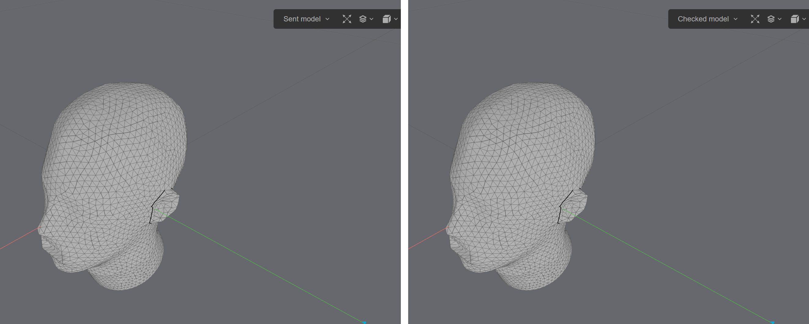
Use Sent model / Checked model at the top of the 3D view to switch between the model you sent and the one the check returned.
Fix a failed check
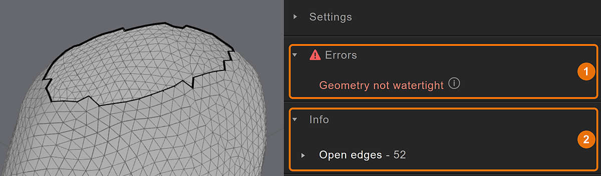
A check fails when a 3D mesh can't be generated, for example when the model isn't closed. Errors (1) then says what went wrong, and Info (2) shows where. Click an entry in Info to highlight it in the model, fix it in your tool and check again.
A failed check has no cost estimate and can't be added to a project.
Compare checks
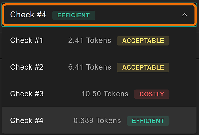
Every check gets a number. Open the dropdown at the top to switch between them. The dropdown shows the estimated token cost and the rating of each check, so you can compare settings and pick the best one. The ratings are:
- Efficient: 15 % mesh quality or more.
- Acceptable: 2 % to 15 %.
- Costly: under 2 %.
Secondary actions
The secondary actions let you change settings or reuse the models. Click ⋮ next to Add to project to open the menu:
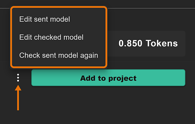
- Check sent model again: use it if the model is as it should be, but you want to try other settings to improve the mesh quality.
- Edit sent model: use it to edit the model you sent before you run another check.
- Edit checked model: use it to edit the checked model and check it again.
Add the checked model to your project
If your model has no errors, you can add it to a project.
-
Click Add to project.

-
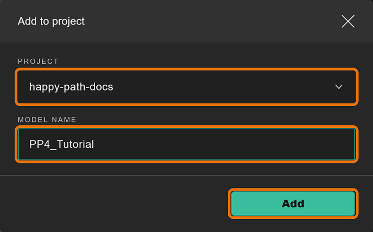
Pick the Project, give the model a Model name and click Add.
-
After that, use Copy ID and Copy name to copy the model's ID or name to the clipboard. You can then paste it in your Python script to fetch the added model:
device_model = project.get_model_by_name("<model_name>")